GENERAL DESCRIPTION Chapter 1
750-177 1-3
3. Modulating Limit Pressure Control (Figure 1-2 and 1-3):
Senses changing boiler pressures and transmits the
information to the modulating motor to change the
burner firing rate when the manual-automatic switch is
set on “automatic.”
4. Low Water Cutoff and Pump Control (Figure 1-2, 1-4
and 1-5): Float-operated control responds to the water
level in the boiler. It performs two distinct functions:
•Stops firing of the burner if water level lowers below the
safe operating point. Energizes the low-water light in the
control panel; also causes low-water alarm bell (optional
equipment) to ring. Code requirements of some models
require a manual reset type of low-water cutoff.
•Starts and stops the feedwater pump (if used) to maintain
water at the proper operating level.
!
DANGER
CAUTION
Determine that the main and auxiliary low
water cutoffs and pump control are level af-
ter installation and throughout the equip-
ment’s operating life. Failure to follow these
instructions could result in equipment dam-
age.
5. Water Column Assembly (Figure 1-2): Houses the low-
water cutoff and pump control and includes the water
gauge glass, gauge glass shutoff cocks.
6. Water Column Drain Valve (Figure 1-2): Provided so
that the water column and its piping can be flushed
regularly to assist in maintaining cross-connecting
piping and in keeping the float bowl clean and free of
sediment. A similar drain valve is furnished with
auxiliary low-water cutoff for the same purpose.
7. Gauge Glass Drain Valve (Figure 1-2): Provided to flush
the gauge glass.
8. Safety Valve(s) (Figure 1-6 and 1-8): Prevent buildup
over the design pressure of the pressure vessel. The size,
rating and number of valves on a boiler is determined by
the ASME Boiler Code. The safety valves and the
discharge piping are to be installed to conform to the
ASME code requirements. The installation of a valve is
of primary importance to its service life. A valve must be
mounted in a vertical position so that discharge piping
and code-required drains can be properly piped to
prevent buildup of back pressure and accumulation of
foreign material around the valve seat area. Apply only a
moderate amount of pipe compound to male threads and
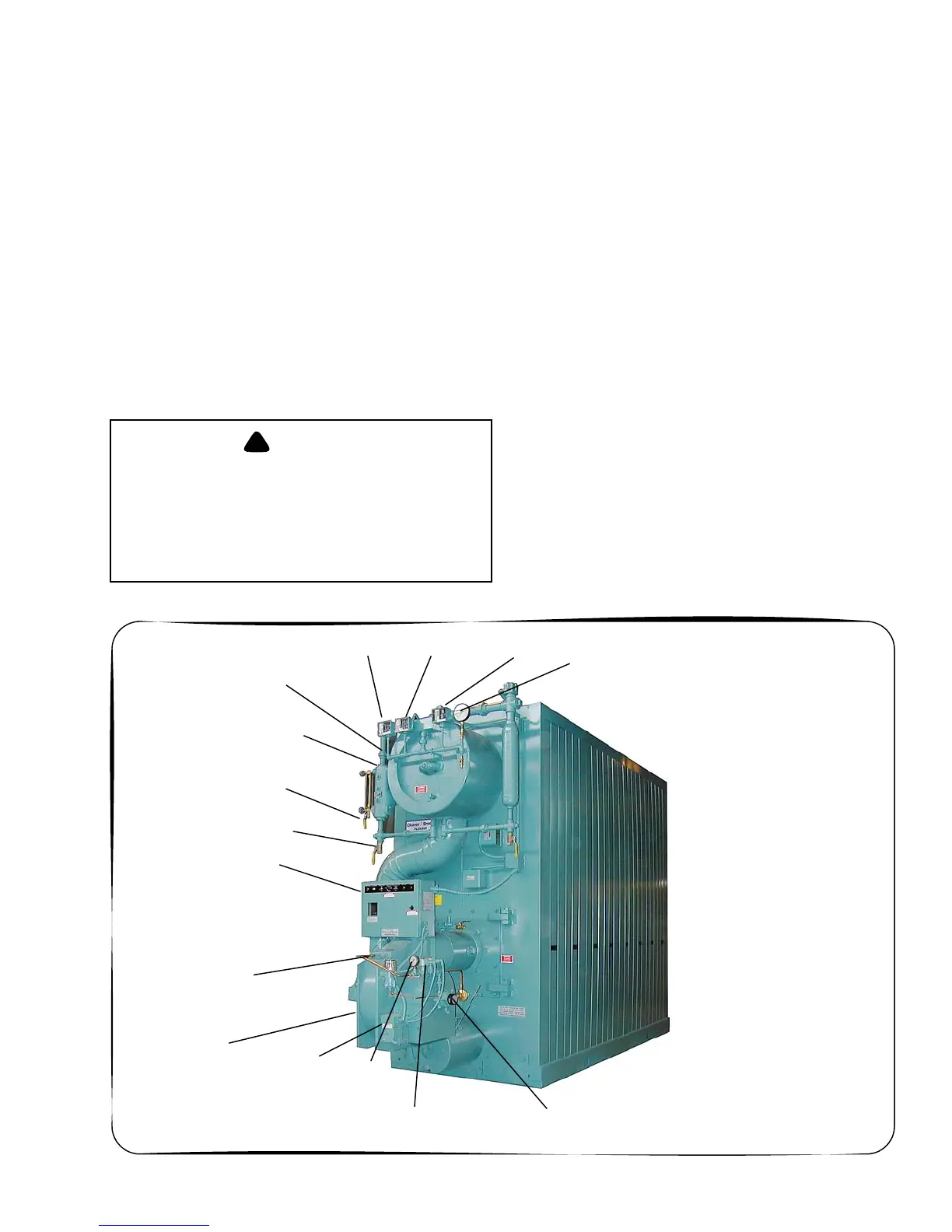
Figure 1-2: Typical Steam Boiler - Light Oil Fired
WATER COLUMN
GAUGE GLASS
DRAIN VALVE
LOW WATER CUTOFF
AND PUMP CONTROL
CONTROL PANEL
FORCED DRAFT
FAN MOTOR
FLAME
DETECTOR
MODULATING
MOTOR
OIL SOLENOID
VALVES
OIL SUPPLY
PRESSURE
GAUGE
HIGH LIMIT
PRESSURE
MODULATING LIMIT
PRESSURE
CONTROLCONTROL
OPERATING LIMIT
PRESSURE
CONTROL
STEAM PRESSURE
GAUGE
WATER COLUMN
DRAIN VALVE
OIL PUMP