Model 4
1500 - 6000 MBTU/hr
Rev. 03-08
Section B2-10
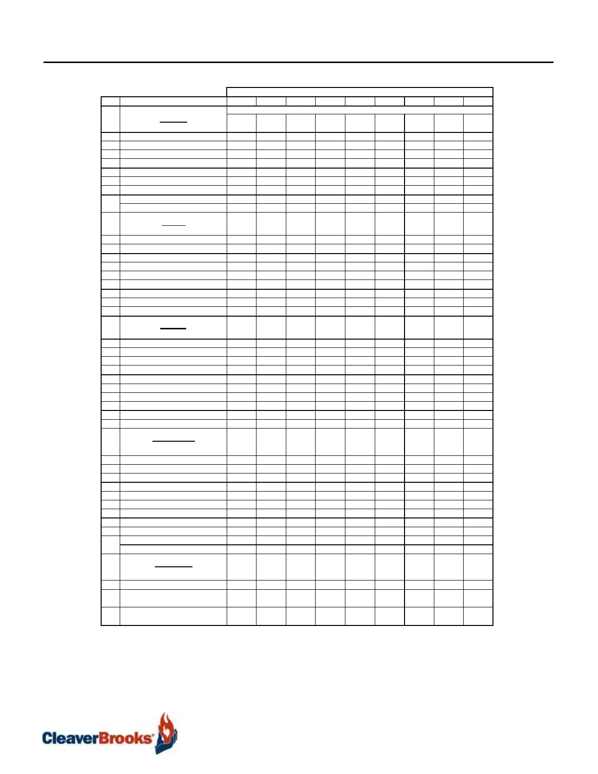
Table
B2-2.
Model
4
Dimensions
Boile
Size
Note
1
1500 2000 2500 3000 3500 4000 4500
5000
6000
A
Lengths
Overall
All
D
imensions are in
inches
84.25 84.25 100.25 100.25 117.375 117.375 136.75
136.75
152.375
B
Pressure Vessel
w/casing
61 61 77 77 92.375 92.375 109
109
124.625
C
Base Fram
e
54 54 69.625 69.625 85.25 85.25 101
101
116.5
C
1
Base to Burner/W
indbox
9.625 9.625 9.625 9.625 9.625 9.625 10
10
10
C
2
Base Fram e Anchor
Holes
51.5 51.5 67.125 67.125 82.75 82.75 98.375
98.375
114
CC
Rear Casing to Stac k Connec
tion
25.8 25.8 26.25 26.25 26.25 26.25 30.375
30.375
30.375
D
Burner/W indbox
Ex
tension
20.1 20.1 20.1 20.1 21.9 21.9 24.6
24.6
24.6
DD
Front Casing to Steam
Nozzle
17.25 17.25 25.25 25.25 30.75 30.75 37.375
37.375
45.25
HH
Steam Nozzle to Safety Valve
15#
8 8 12 12 11.5 11.5 13
13
17
Steam Nozzle to Safety Valve
150#
8 8 12 12 17 17 17
17
17
E
Widths
Overall
53.25
53.25
53.25
53.25
53.25
53.25
53.25
53.25
53.25
F
Center to Water
Column
32.4 32.4 32.4 32.4 32.4 32.4 32.4
32.4
32.4
G
Center to Opt. Aux.
W
ater
C
olum
n
26.6 26.6 26.5 26.6 26.6 26.6 26.6
26.6
26.6
H
Center to Outside
Casing
16.375 16.375 17.375 16.375 16.375 16.375 16.375
16.375
16.375
I
Base Fram e
Inside
20 20 20 20 20 20 20
20
20
J
Base Fram e
Outside 28 28 28 28 28 28 28
28
28
K
Soot Washers, Center to
Center
21.4 21.4 21.4 21.4 21.4 21.4 21.4
21.4
21.4
L
Boiler Centerline to Soot
Washer
10.7 10.7 10.7 10.7 10.7 10.7 10.7
10.7
10.7
M
Boiler Centerline to Base Centerli
ne
12 12 12 12 12 12 12
12
12
N
Boiler Centerline to Soot
Drain
5.25 5.25 5.25 5.25 5.25 5.25 5.25
5.25
5.25
OO
Heights
Overall [Base to Stack
Connection]
78.75
78.75
78.75
78.75
78.75
78.75
78.75
78.75
78.75
O
Base to Steam Nozzle
150#
74.75 75.75 74.75 74.75 74.75 74.75 78
78
78
O
Base to Steam Nozzle
15#
75 75 75 75 78.25 78.25 78.25
78.25
78.25
O
1
Base to Stack
Box.
77.8 77.8 77.8 77.8 77.8 77.8 77.8
77.8
77.8
O
2
Base to Top of Control
Panel
83.25 83.25 83.25 83.25 83.25 83.25 83.25
83.25
83.25
P
Base to Surface
Blowoff
59.25 59.25 59.25 59.25 59.25 59.25 59.25
59.25
59.25
Q
Base to Feedwater
Inlet
57.25 57.25 57.25 57.25 57.25 57.25 57.25
57.25
57.25
R
Base to Soot Washer
Lance
55.5 55.5 55.5 55.5 55.5 55.5 55.5
55.5
55.5
S
Height of
Base
4 4 4 4 4 4 4
4
4
OS
Base to Oil Supply
Connection
27.75 27.75 27.75 27.75 27.75 27.75 27.75
27.75
27.75
OR
Base to Oil Return
C
onnection
25.75 25.75 25.75 25.75 25.75 25.75 25.75
25.75
25.75
BB.
Connections
OD Stac k - Sleeve
C
onnection
12
12
12
12
12
12
16
16
16
T
Bottom Drum Blow Down, 15#
[one]
1.25 1.25 1.25 1.25 1.5 1.5 1.5
1.5
1.5
T
1
Bottom Drum Blow Down, 150#
[one]
1.25 1.25 1.25 1.25 1.25 1.25 1.25
1.25
1.25
U
Steam Nozzle,
15#
4
A
4
A
4
A
4
A
6
B
6
B
6
B
6
B
6
B
V
Steam Nozzle,
150#
2.5
A
2.5
A
3
A
3
A
3
A
3
A
4
B
4
B
4
B
W
Soot Washer
D
ra in s
[Two]
2 2 2 2 2 2 2
2
2
X
Surface Blow off
[One]
0.75 0.75 0.75 0.75 0.75 0.75 0.75
0.75
0.75
Y
Feedwater Inlet
[One]
1 1 1 1 1 1 1
1
1
Z
Soot Washer
[Two]
0.25 0.25 0.25 0.25 0.25 0.25 0.25
0.25
0.25
GG
Oil Supply and
Return
0.5 0.5 0.5 0.5 0.5 0.5 0.5
0.5
0.5
JJ
Relief Valve,
15#
2 2 2 2 2 2.5 2.5
2.5
3
Relief Valve,
150#
1 1.25 1.25 1.25 1.5 1.5 1.5
1.5
2
EE
Clearances
Burner/W indbox
Sw
ing
33
33
33
33
33
33
33
33
33
FF
Tube removal eac h
s
ide
30 30 30 30 30 30 30
30
30
RF
Allowance for
Burner/Windbox Swing
and 30" Rear Aisle
Space.
124 124 140 140 155 155 172
172
187
RD
Allowance for Tube Removal
Each
Side and
Burner/Windbox Swing.
93 93 93 93 93 93 93
93
93
NOTES: 1.
The above dimensions,
while
sufficiently accurate
for layout
purposes,
must be
confirmed
for
construction
via certified
prints.
For
200
PSIG design pressure
and
greater, contact Milwaukee Sales
for
certified
prints.
2. Allow
sufficient space
at
rear
of boiler for
removal
of
soot washer
lance.
3.
For access
to the
furnace,
a 13" x 21"
access door
is
provided behind
the front door.
4.
Control Panel
may be
larger
(up to 4" in
height)
if
certain control options are
provided.
A.
Connection
is a
Female Pipe
Thread.
B.
Connection
is a
150#
Flange,
Flat Face.