Model 4
1500 - 6000 MBTU/hr
Rev. 03-08
Section B2-4
PRODUCT OFFERING
The
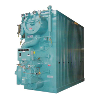
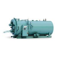
Model 4 (M4) Boiler is a
compact carbon
steel,
extended
fin,
watertube
boiler.
Heat transfer design is
configured
in a "3-pass" gas travel across the watertube
surfaces. The pressure vessel
is
constructed
to
conform
to the
A.S.M.E. Code,
either
Section
IV for low
pressure steam
@ 15
PSIG MAWP (maximum allowable
working
pressure)
or
Section
I for
MAWP greater
than 15 PSIG.
The vessel (boiler) consists of two rows on each side of the vessel, of formed
seamless tubes
with
extended
fin
surfaces
and
downcomers connected
to the steam
drum and lower drum. To reduce standby losses, the
vessel
is insulated with a
fiberglass blanket
and
removable steel
jacket.
Complete with an integral burner for either No.2 fuel oil or Natural Gas, the
complete burner/boiler package
is UL
Approved,
listed, and labeled.
Standard
Equipment
The standard boiler/burner package
is
described
below.
Optional controls,
trim, and
devices
may be added to meet project
requirements.
Some of those options are
noted following
this
standards
li
st.
1. Boiler
A. Designed, constructed, and hydrostatically tested in accordance with the
A.S.M.E. Boiler and
Pressure Vessel
Code. The
complete vessel
is mounted on a
structural steel
frame.
B. Steam drum includes a hand hole in the rear head for drum water side
inspection.
Connections are included
for the following:
•
Feedwater Makeup
w/internal
dispersion
tube.
•
Surface
Blowoff.
•
Steam
Supply.
•
Safety Relief
Valve.
C.
Lower
Drum
includes
hand
holes
at
each
end for
waterside
inspection. A drain/
blowoff tapping is
provided
at the front, bottom
centerline.
D. Soot washer lances are provided on each side of the
vessel
between the two
rows of
tubes
for
fireside
cleaning.
Soot washer drains are located
at the bottom of
the boiler, with
connections
to drain
located
on
each
side of the lower drum at the
rear.
E.
Refractory
is limited to the furnace floor, lower drum, and burner throat
tile.
High
temperature
insulation is installed on the front water wall and
furnace access
door.
F. Two lifting
eyes
are
provided
on the top
centerline
of the upper drum for
ease
of
installation.
G.
Furnace inspection/access door
is
provided
in the
furnace
front
wall.
H. The
exhaust gas
vent is
located
at the top rear
centerline
of the boiler. A stack
thermometer
is shipped
loose
for field installation by the installing
contractor
into
the stack.
I. The
complete vessel
is fully
insulated
(2"
fiberglass
blanket) under a preformed,
sectional steel
jacket.
 Loading...


