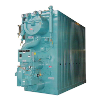
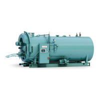
Model 4
1500 - 6000 MBTU/hr
Rev. 03-08
Section B2-29
E.
The maximum sound level
shall not
exceed
80
dBA measured
3 feet
in front of the boiler.
2.3
PRODUCT
DESIGN
A.
Pressure Vessel
1.
The upper
drum shall
have
a 20"
OD, manufactured
from
SA–
53 Gr. B
seamless
pipe, with a minimum wall
thickness
of
0.3
75".
2.
The
lower drum shall
have
an 8–5/8"
OD, manufactured
from
SA–53
Gr. B
seamless
pipe, with a minimum wall
thickness
of
0.3
22".
3.
The generating tubes
shall be 2"
OD, manufactured
from SA–
178 Gr. A tubing, with a minimum wall
thickness
of
0.
095".
4.
The
boiler shall
have
two
downcomers, located
at the
rear
of
the boiler, and be totally
insulated
from the
generating
tubes.
These
shall be a minimum of 2–1/2"
OD, manufactured
from
SA–178 Gr. A tubing, with a minimum wall
thickness
of
.
105".
5.
The upper
drum shall
have
an
inspection opening, located
at
the
rear
of the unit, to allow internal
inspection,
and shall be a
minimum of 4"x6".
6.
The
lower drum shall
have inspection openings, located
at the
front and
rear
of the unit, to allow
internal inspection, and
shall
be a minimum of 4-7/8" x
5-7
/
8
"
.
7.
The
boiler shall
have inspection openings
in the
convection
area.
8. A
feedwater
tapping and
integral feedwater
distribution pipe
shall be
located
in the
upper
drum.
The
distribution pipe shall
blend the
feedwater
with the boiler water.
9. A
3
/
4
"
surface
blowoff
connection
shall be
located
in the rear
head
of the
upper
drum.
10. A
"
bottom blowoff
connection
shall be
located
in the
lower drum.
B.
R
e
fr
actor
y
1.
Refractory
shall be limited to the
furnace
floor to
insulate
the
lower drum, and to the
burner
throat tile
.
2. High
temperature insulation
shall be
installed
on the front wall
of the furnace.
C.
Insulation
and
Casing
1.
The
boiler
insulation
shall be a minimum of 2"
fiberglass,
and
shall
cover
the
entire pressure
vessel.
2.
The insulation
shall be
covered
with a
corrugated
metal
lagging.
3.
The
metal
lagging
and
insulation
shall be
arranged
for easy
removal
and
installation
if required.
4.
The
front
head (windbox)
shall be
attached
with a davit arm,
gasket sealed,
and bolted.
The
front
head
shall swing
open
to
provide
full
access
to the
furnace chamber
and
burner
throat
tile.
 Loading...


