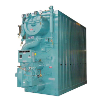
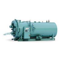
Model 4
1500 - 6000 MBTU/hr
Rev. 03-08
Section B2-30
5.
Observation ports shall be provided
at
each end
of the
boiler
for
visual inspection
of the pilot and main flame conditions.
6. Two lifting
eyes
shall be
located
on top of the boiler.
7.
The exhaust gases
shall
vent
at the
rear
of the boiler, on the top
centerline.
D.
T
r
im
1.
The water column
shall
be located
on the left
side
of the boiler.
It shall be piped with
unions
for
easy
removal.
2. A
gauge glass
set,
gauge glass blowdown valve,
and water
column
blowdown valve
shall be provided.
3.
The
boiler
feedwater control
switch shall be
included
as an
integral
item of the water column. It shall
provide
automatic
actuation
of a motor
driven feedwater
pump or
valve
to
maintain the boiler water
level
within normal
limits.
4.
The primary
low
water
cutoff switch shall be an
integral
part of
the water column. It shall be wired into the
burner
control
circuit
preventing burner operation
if the boiler water
level
falls
below the
designated safe
level.
5. A
steam pressure gauge
shall be
located
at the front
end
of the
boiler and shall include a
cock
and test connection.
6. A
safety
relief
valve
shall be
provided
of a
size
and type to
comply with
ASME Code
requirements.
The safety
relief valve
set
pressure
shall be psig.
7. A high limit
pressure
control shall be provided. It shall be a
manual
reset
type and shall be wired to
prevent
burner
operation
and
lockout
if
excessive steam pressure
occurs.
8.
An operating
limit
control shall be
provided. It shall
be wired
to
provided
on– off control of the
burner
at
operating
set points.
9. A firing
rate control
shall be provided. It shall control the firing
rate of the
burner based
on the boiler load.
10. An
auxiliary
low water cutoff shall be
provided (manual
reset
type).
It shall
be
wired into the
burner control
circuit
preve
n
ting
burner operation
if the boiler water
level
falls below the
designated safe
level.
11. A
stack thermometer
shall be
shipped loose
for field
installation.
E.
Soot Clean
i
ng
1.
Soot washer lances
shall be
provided
in the
convection area
of
the boiler
measuring
the full
length
of the
pressure
vessel.
2.
Each lance
shall be
provided
with a shutoff
valve
and the
assembly
shall be
capable
of
rotating
360 degrees. This shall
ensure complete washing
of the
convection zone
while the
boiler is
operating
in the low fire mode.
3.
Soot washer troughs
shall be
provided
at the bottom of the
boiler.
These
shall be
furnished
for
each convection side
and
shall
The soot washer troughs
shall be
provided
with 2" drain
connections
at the
rear
of the boiler, and shall
have
inspection/
cleanout openings
at the front of the boiler.
 Loading...


