Do you have a question about the Clevo N131BU and is the answer not in the manual?
Precautions to reduce risk of fire, electric shock, and injury when using electrical equipment.
Suggestions to prevent damage to the notebook computer.
Specific power requirements for the computer; adapter and plug safety.
Precautions for battery usage, charging, repair, handling, and storage guidelines.
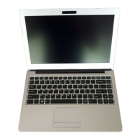
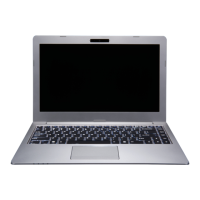
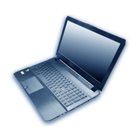
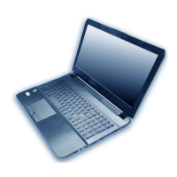
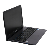
Detailed technical specifications of the notebook's components and features.
Further specifications including M.2 slots, interface ports, communication modules, power, and dimensions.
Shows the top side of the mainboard, highlighting key components.
Shows the bottom side of the mainboard, highlighting key components like CPU and memory slots.
Identifies connectors on the top side of the mainboard.
Identifies connectors on the bottom side of the mainboard.
Lists recommended tools for working on the notebook PC.
Reminders to avoid personal injury or damage during removal/replacement.
Table listing disassembly steps and corresponding page numbers for reference.
Step-by-step guide for removing the keyboard module and its ribbon cable.
Detailed instructions for safely removing the computer's battery.
Guide for removing the 2.5" SATA HDD/SSD drive from the mainboard.
Instructions for removing and installing SO-DIMM RAM modules from the memory sockets.
Step-by-step guide for removing the Wireless LAN module from the mainboard.
Procedure for removing the 3G module, including cable disconnection and screw removal.
Guide for removing and installing M.2 SSD modules (SSD-1 and SSD-2).
Instructions for removing the CCD module, involving prying the LCD front cover.
Overall system block diagram showing major components and their interconnections.
Schematic detailing processor signals and their connections, part 1 of 10.
Schematic detailing processor signals, including display interfaces (MDP, HDMI, EDP) and CSI-2.
Schematic detailing processor signals related to PCIe, USB 3.0, SATA, and SSIC interfaces.
Schematic detailing processor signals for clock signals, thermal sensors, and JTAG interface.
Commands and steps to execute the BIOS flashing utility from the EFI Shell.
Final steps to restart the computer, enter BIOS, load defaults, and save changes.
| Operating System | Windows 10 |
|---|---|
| Weight | 1.5 kg |
| Storage | 1 x 2.5" SATA HDD/SSD (7mm) |
| Display | 13.3" HD (1366x768) / FHD (1920x1080) LED Backlit |
| Battery | 36Wh |