Disassembly
2 - 14 Removing and Installing a Processor
2.Disassembly
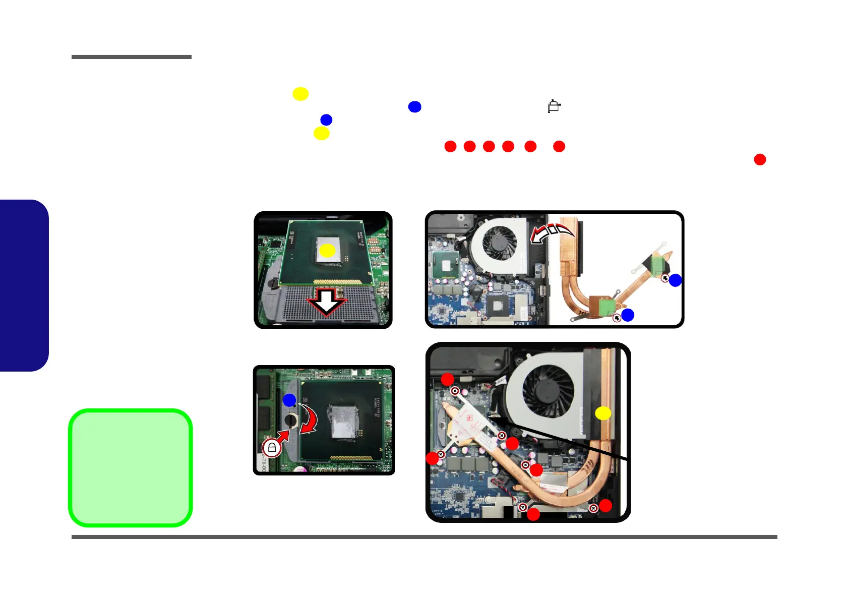
Processor Installation Procedure
1. Insert the CPU (Figure 10a), pay careful attention to the pin alignment, it will fit only one way (DO NOT
FORCE IT!), and turn the release latch towards the lock symbol (Figure 10b).
2. Remove the sticker (Figure 10c) from the heat sink.
3. Insert the heat sink
as indicated in Figure 10d.
4. Tighten the CPU heat sink screws in the order
, , , , & (the order as indicated on the label and
Figure 10d) *
Note: Make sure that the size of the screwdriver is below 4mm. when removing or tighting screw ,
and its position should be at a 90 degree angle from the mainboard.
5. Replace the component bay cover (don’t forget to replace the fan cable) and tighten the screws (page 2 - 6).
b.
B
a.
D
1
3
5
Note:
Tighten the screws
in the order as indi-
cated on the label.
C
A
c.
d.
2
4
6
Lock
C
Figure 10
Processor
Installation
a. Insert the CPU.
b. Turn the release latch to-
wards the lock symbol.
c. Remove the sticker from
the heat sink and insert
the heat sink.
d. Tighten the screws.
A. CPU
D. Heat Sink
•6 Screws
 Loading...