15
Tranquility
®
Digital Air Handler (TAH)
Rev.: 11 Feb., 2013
Electrical - Thermostat Wiring
Thermostat Installation
The thermostat should be located on an interior wall in a
larger room, away from supply duct drafts. DO NOT locate
the thermostat in areas subject to sunlight, drafts or on
external walls. The wire access hole behind the thermostat
may in certain cases need to be sealed to prevent erroneous
temperature measurement. Position the thermostat back
plate against the wall so that it appears level and so the
thermostat wires protrude through the middle of the back
plate. Mark the position of the back plate mounting holes
and drill holes with a 3/16” (5mm) bit. Install supplied
anchors and secure plate to the wall. Thermostat wire must
be 18 AWG wire. Wire the appropriate thermostat as shown
in Figures 6 and 7 to the low voltage terminal strip on the
ECM control board. Practically any heat pump thermostat
will work with these units, provided it has the correct number
of heating and cooling stages.
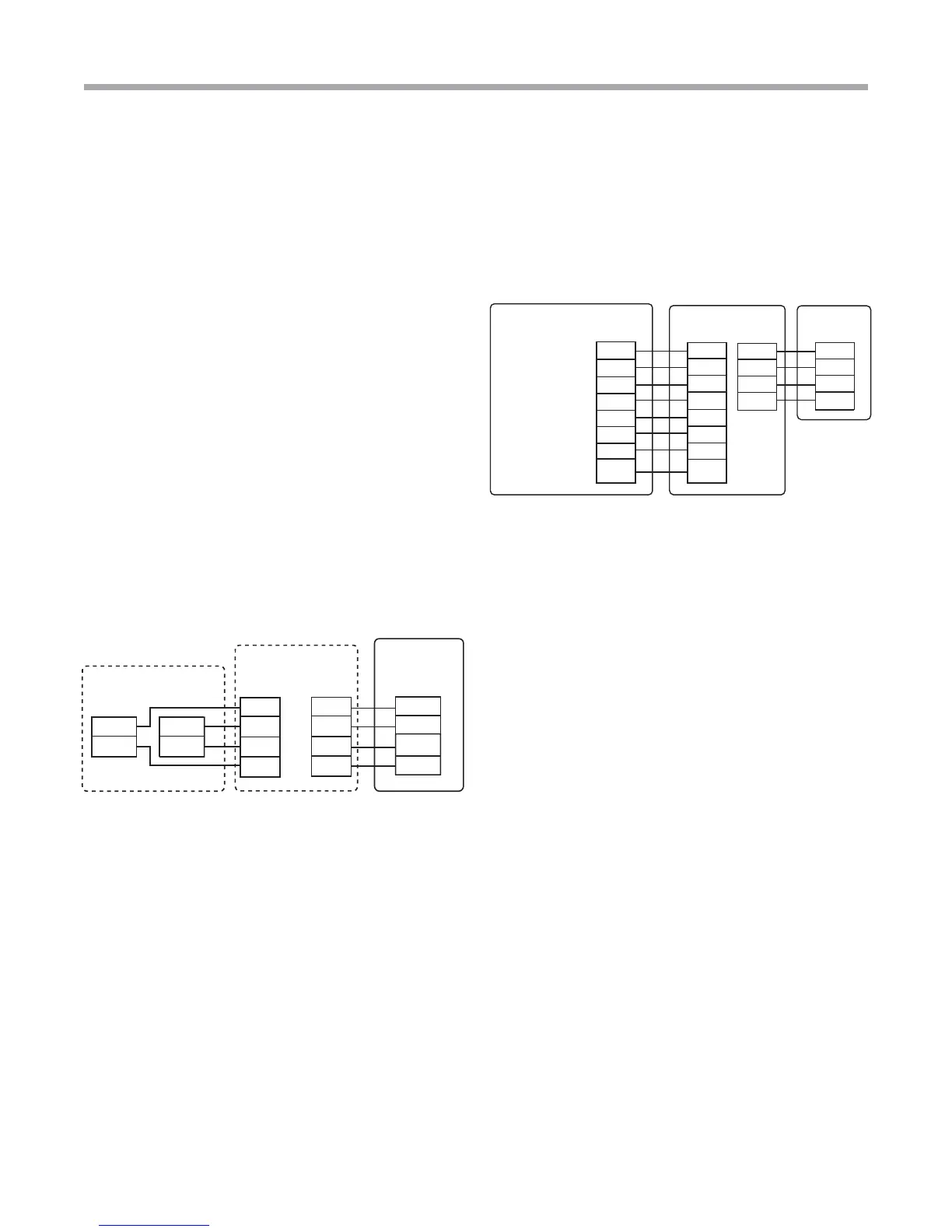
4-Wire Connection ATC communicating thermostat and
DXM2 Communicating control in Tranquility
®
Digital Splits
AXM control in Tranquility
®
Digital Air Handler allows
4-wire connection with Communicating DXM2 board and
Communicating ATC Thermostat.
Thermostat Connections
C 24V Common for Control Circuit
R 24V Supply for Control Circuit
A+ Communications (Positive)
B – Communications (Negative)
iGate
™
Thermostat
ATC32**
DXM2 in
Compressor
Section
Communicating
TAH with
AXM Control
R
A+
A+
B-
B-
C
R
C
24V
A+
B-
C
24V
A+
B-
C
Figure 6: 4-Wire
Connection to ATC communicating
thermostat, AXM Communicating control
and Tranquility
®
Digital Splits
Connection to Non-Communicating thermostat, AXM
communicating control in Tranquility
®
Digital Air Handler
and Tranquility
®
Digital Splits
Figure 7:
Connection to Non-Communicating
thermostat and AXM communicating control
in Tranquility
®
Digital Air Handler
Non-Communicating
2 Cool / 3 Heat Thermostat
Compressor
Compressor Stage 2
Communicating
TAH AXM Control
Y1
Y2
O
R
G
C
DH
AL1
Y1
Y2
DXM2 In
Compressor
Section
Fault LED
L
Reversing Valve O
24Vac Hot
R
Fan
G
24Vac Common
C
DH
Dehumidification
(ATP32U04 Only)
C
A+
B-
24V
C
A+
B-
24V
Thermostat Connections
C 24V Common for Control Circuit
R 24V Supply for Control Circuit
A+ Communications (Positive)
B – Communications (Negative)