19
Tranquility
®
Digital Air Handler (TAH)
Rev.: 11 Feb., 2013
Overview
The AG Series Auxiliary Electric Heat mounts internally in
upfl ow (Figure 11) or downfl ow units and horizontal units.
Horizontal units are rated for zero clearance at the unit
and 1" clearance for fi rst three feet of duct, vertical units
rated for zero clearance for both unit and duct. Downfl ow
units can not be located directly over a discharge register.
The discharge plenum must be constructed from non
combustible material. The AG electric heat contains a four
stage relay control board which activates the elements
directly via an internally wired low voltage harness. Low
voltage signals (W1 and W2) are staged from the AXM
control.
Vertical Upfl ow or Downfl ow and Horizontal Installation
1. Disconnect power to the unit
2. Remove blower access panels.
3. Clip wire-tie holding electric heat low voltage 3-wire
harness to discharge panel stiffener.
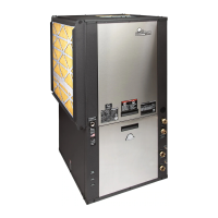
4. Remove blower mounting screws and then drop down
blower assembly as shown in Figure 12. Removal of
blower wires should not be necessary.
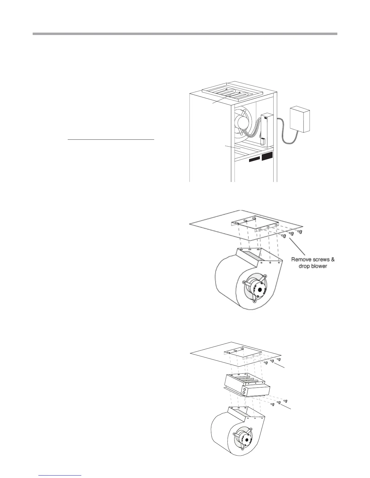
5. Install electric heat in discharge fl ange where blower
assembly has been removed using provided screws as
shown In Figure 13.
5.5 For downfl ow or horizontal right discharge units, the
air handler support bracket must be removed to re-
install the blower housing assembly. After re-installing
the blower housing, re-install the air handler support
bracket.
6. Re-install blower assembly, Figure 13, into electric heat
assembly using blower mounting screws. Check blower
wiring for proper wiring connections.
7. Route the low voltage harness through the provided
‘pie’ bushing and plug into electric heat control board
connector P2 as shown in Figure 18.
8. Install power conduit through unit corner post knockout
and attach conduit directly to the electric heat control
box.
9. Optional: AG**C kits only. Blower power may be supplied
from T3 & T4 CB5 breaker. Refer to wiring diagram
96B0143N01.
Electric Heat Installation
Locate electric heat assembly
on pins in discharge panel
and insert screws
Relocate blower in electric
heat assembly in same
manner
Figure 12: Blower removal
Figure 13: AG electric heat mounting and
blower re-installation
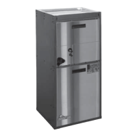
Figure 11: Typical air handler installation
Route condiut thru cabinet and
connect to electric heat control
box. Seal to eliminate air leaks on
cabinet exterior.
Low voltage control
harness is prewired
on all distributor class units.
Electric Heat
Assembly
Auxiliary electric heat
power supply knockout
opposite air coil
Disconnect (optional
refer to local code)
Air Coil