Tranquility
®
Digital Air Handler (TAH)
Rev.: 11 Feb., 2013
20
Geothermal Heat Pump Systems
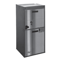
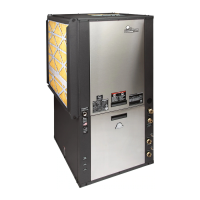
Figure 14: Power Wiring, Dual Circuits, 15 and 20kw Figure 15: Power Wiring, Single Circuit, 15, 20kw
Wiring and Setup (all models)
1. Install power wiring and connect to power block or
circuit breakers. In 12, 15 or 20kW models two power
circuits may be used to reduce wiring and breaker
costs as in Figure 14. If a single circuit supply is
desired, install the optional single circuit accessory kit
(P/N 16B0002N02), as shown in Figure 15, that can be
obtained from your distributor.
2.
Ensure unit airfl ow setting is above minimum airfl ow rating
for the electric heat model from Table 1.
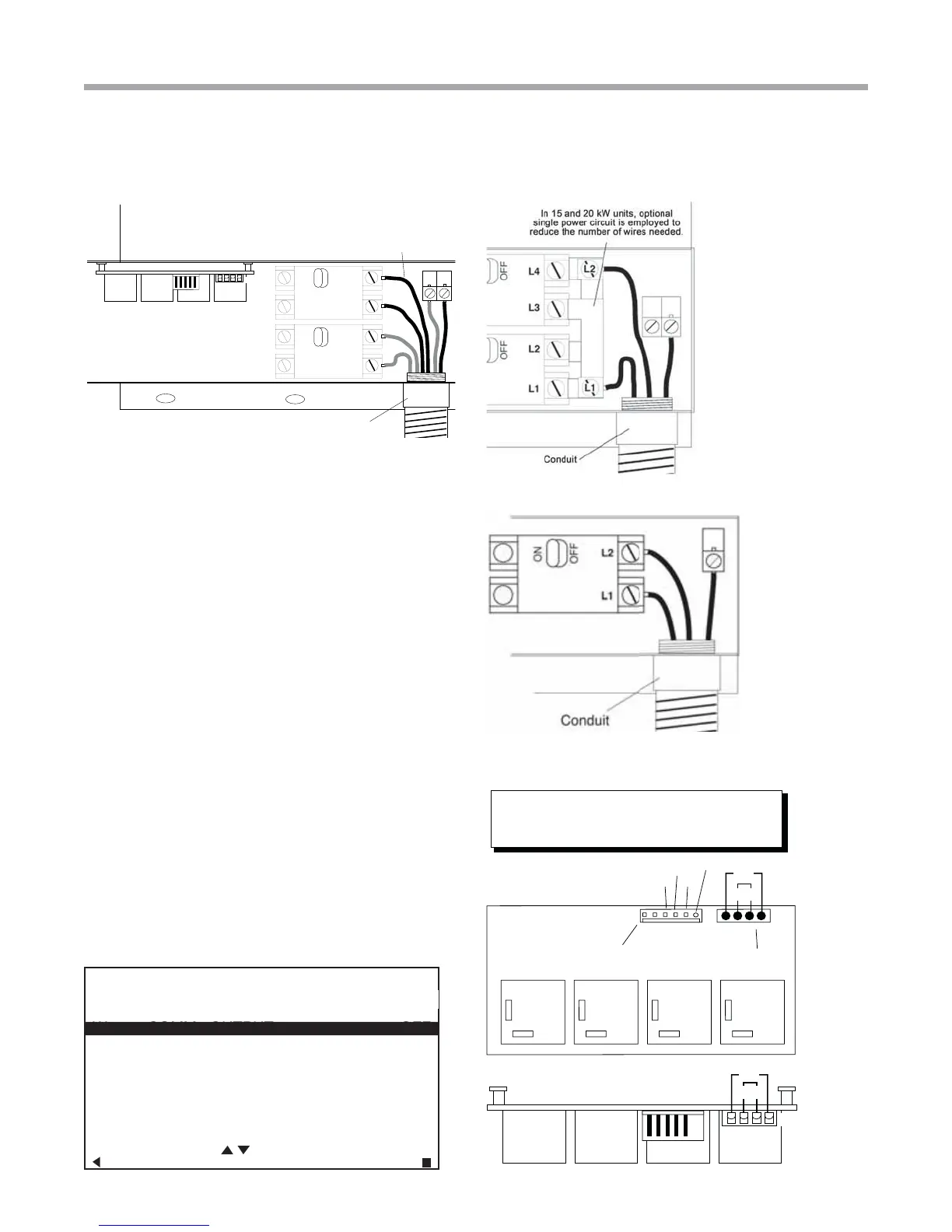
3. Check staging jumpers for the application. Typically
only 5 kW (factory setting on all models except 10kW on
20kW models) is needed for fi rst stage electric (W1) to
minimize electric demand. This staging can be adjusted
by moving the staging jumpers as shown in Figure 17.
Whatever is jumped to P1 pin 1 will be energized on
1st stage of electric heat, and P1-2 will be energized as
stage 2 electric heat. See Table C for staging options.
4. Mark the appropriate box of the electric heat model
installed on the additional serial plate on the exterior of
the unit.
5. Turn on the power to the unit and the auxiliary
electric heat.
Auxiliary Electric Heat Start-up
Put thermostat in emergency heat mode in manual mode on
ATC/ACD (see fi gure #) and setpoint to high setting. Unit will
require 15-20 seconds before engaging emergency heat mode
stage 1 (W1) and then another 15-20 seconds to engage
stage 2 (W2) when in ‘Test mode’. Verify proper electric heat
operation. Exit manual mode for normal operation.
NO
Com
ER1
NO
Com
ER2
NO
Com
ER3
NO
Com
ER4
123
Tan
Ora
Factory Staging
(see Table 2)
Low Voltage Connector
(from Unit Control Board)
AG Electric Heat
Relay Board
P1P2
24V
W1
W2
4
5kW (‘ER1’ 5kW & ‘ER4’ 0kW) and W2 (second stage)
will have 10kW (‘ER2 & 3’ 5kW each)
1234
Tan
Ora
P2
Side View as seen in Control Box
P1
Staging Example on a 15kW unit W1 (first stage) has
blank
Figure 17: Staging Jumpers
Figure 16: Power Wiring, 4, 5, 8, and 10kw
Electric Heat Wiring
21
2))
21
2))
3
,QDQGN:XQLWV
WZRSRZHUFLUFXLWVDUH
HPSOR\HGWRUHGXFHZLUHV
VL]HDQGFRVWRIEUHDNHUV
/
/
/
/
3
&RQGXLW
MANUAL OPERATING MODE
Y1 COMM OUTPUT OFF
Y2 COMM OUTPUT OFF
W COMM OUTPUT OFF
O COMM OUTPUT OFF
G COMM OUTPUT OFF
H COMM OUTPUT OFF
DH COMM OUTPUT OFF
ECM AIRFLOW 0
PUMP SPEED 0%
TEST MODE OFF
SELECT OPTION
PREVIOUS SELECT
Y1 COMM OUTPUT OFF
W COMM OUTPUT OFF