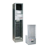
EasyManua.ls Logo

ClimateMaster TRM Series - User Manual

ClimateMaster TRM Series
50 pages
Print Icon
To Next Page IconTo Next Page
Loading...
Tranquility
Modular
(TRM Series)
Vertical Stack
(VHS) Series
Commercial Vertical Stack
Water-Source Heat Pumps
Installation, Operation &
Maintenance Instructions
97B0056N01
Revision: Nov. 5, 2009B
Table of Contents
Model Nomenclature 3
General Information 7
Riser & Cabinet Installation 9
Cabinet Installation 12-14
Piping Installation 15
Water-Loop Heat Pump Applications 16
Ground-Loop Heat Pump Applications 16
Ground-Water Heat Pump Applications 18
Water Quality Standards 20
Electrical Wiring - Line Voltage 21
Electrical Wiring - Low Voltage 22
Thermostat Installation 23
Chassis Pre-Installation 24
Unit Start-Up Preparation 27
Hose Kit & Chassis Installation 28
CXM Controls 32
DXM Controls 33
Safety Features - CXM/DXM Controls 35
Unit Commissioning
and Operating Conditions 36-37
Piping System Cleaning and Flushing 37
Unit and System Checkout 38
Unit Start-Up Procedures 39
Unit Operating Conditions 40-42
Start-Up Log Sheet 43
Preventative Maintenance 44
Troubleshooting 45-46
Troubleshooting Form 47
Warranty 48
Revision History 50

Questions and Answers

  • T
    Thomas ArmstrongAug 10, 2025
    What to do if my ClimateMaster TRM Heat Pump has main power problems?
    • D
      Deanna LarsenAug 10, 2025
      If your ClimateMaster Heat Pump has main power problems, start by checking the line voltage circuit breaker and disconnect if the green status LED is off. Next, check for line voltage between L1 and L2 on the contactor, and then check for 24VAC between R and C on the CXM/DXM. Finally, verify the primary/secondary voltage on the transformer.
  • M
    Mary LopezAug 15, 2025
    What to do if my ClimateMaster TRM Heat Pump shows FP1 Fault - Code 4 Water Coil low temperature limit?
    • A
      Andrew KimAug 15, 2025
      If your ClimateMaster Heat Pump shows FP1 Fault - Code 4, indicating a water coil low-temperature limit issue, it could be due to several reasons. Check for reduced or no water flow in heating by inspecting the pump operation or water valve operation/setting. Also, inspect for a plugged strainer or filter and clean or replace it. Ensure proper water flow rate and adequate antifreeze level by checking the antifreeze density with a hydrometer. Verify the temperature limit setting (use JW3 jumper for antifreeze at 10°F [-12°C]) and ensure the water temperature is within the design parameters. Lastly, check the thermistor by comparing its temperature and impedance correlation per the chart.
  • D
    Douglas GentryAug 20, 2025
    What to do if my ClimateMaster TRM Heat Pump shows LP/LOC Fault-Code 3 Low Pressure/Loss of Charge?
    • J
      James HughesAug 20, 2025
      If your ClimateMaster Heat Pump displays LP/LOC Fault-Code 3, indicating low pressure or loss of charge, it may be due to insufficient charge. Check for refrigerant leaks and verify the charge and start-up water flow.
  • E
    Erica MarshAug 26, 2025
    What to do if my ClimateMaster Heat Pump shows FP2 fault - Code 5 Air Coil low temperature limit?
    • C
      Chelsea HuntAug 26, 2025
      If your ClimateMaster Heat Pump shows FP2 fault - Code 5, indicating an air coil low temperature limit, check for reduced or no airflow in cooling by inspecting for a dirty air filter and cleaning or replacing it. Also, check the fan motor operation and airflow restrictions. Ensure that the external static is not too high by checking the static vs. blower table. Verify that the air temperature is within the appropriate range. For normal airside applications, a 30°F [-1°C] setting is typically required. Finally, check the thermistor by comparing its temperature and impedance correlation per the chart.
  • H
    howard48Aug 30, 2025
    How to fix a Condensate Fault-Code 6 on a ClimateMaster TRM Heat Pump?
    • A
      Alan MeyersAug 30, 2025
      To address a Condensate Fault-Code 6 on your ClimateMaster Heat Pump, begin by checking for a blocked drain and cleaning it. Inspect the trap dimensions and ensure its location is ahead of the vent. Verify proper drainage by confirming the piping slopes away from the unit and check the unit's slope toward the outlet. Ensure proper venting by checking the vent location. Look for moisture shorting to the air coil and replace the air filter if it's plugged. Finally, identify and eliminate any restrictions to return airflow, and consider increasing the return duct and/or grille size if needed.
  • N
    Nicholas SmithNov 4, 2025
    What to do if my ClimateMaster TRM shows HP Fault-Code 2 High pressure?
    • L
      Lisa PetersenNov 4, 2025
      If your ClimateMaster Heat Pump displays HP Fault-Code 2 indicating high pressure, several factors could be the cause. If in cooling mode, check for reduced or no water flow by inspecting the pump and valve operation/setting, and ensure the water temperature is within the design parameters. If in heating mode, check for reduced or no airflow by inspecting for a dirty air filter and cleaning or replacing it, check the fan motor operation and airflow restrictions. Other potential issues include a dirty air coil, excessive external static pressure (compare static to the blower table), return air temperature outside the design range, overcharging of refrigerant (check superheat/subcooling against the typical operating condition table), or a faulty HP switch (check switch continuity and operati...

Summary

Accessory Nomenclature

Return Air Panel

Details about return air panels and their nomenclature.

Supply Air Grille

Details about supply air grilles and their nomenclature.

Hose Kit

Details about hose kits and their nomenclature.

General Information

Safety

Important warnings, cautions, and notices regarding unit operation and safety.

Riser & Cabinet Installation

Supply and Return Piping

Guidelines for installing supply and return piping systems for the unit.

Condensate Piping

Information on connecting the condensate drain pan assembly and riser.

Riser Connections

Details on accommodating expansion/contraction and alignment of riser connections.

Cabinet Installation

Steps for correctly positioning and installing the unit cabinet.

Cabinet Installation

Supply Grille Installation

Instructions for installing the supply grille into the cabinet opening.

Piping Installation

Installation of Supply and Return Piping

Comprehensive guidelines for installing supply and return piping.

Water-Loop Heat Pump Applications

Commercial Water Loop Applications

Specifics for commercial systems using common piping and air elimination.

Ground-Loop Heat Pump Applications

Industry-accepted practices for installing closed-loop earth-coupled heat pump systems.

Ground-Water Heat Pump Applications

Open Loop - Ground Water Systems

Guidelines for open loop systems, including shut-off valves and piping materials.

Water Quality Standards

Criteria for assessing water quality and its impact on system components.

Expansion Tank and Pump

Recommendations for sizing and selecting expansion tanks and pumps.

Water Control Valve

Guidance on placing control valves on the discharge line for proper operation.

Electrical Wiring - Line Voltage

Blower Speed Selection - Units with PSC Motor

How to change blower fan speed for PSC motors.

Blower Speed Selection - Units with ECM-X Motor

How to change blower fan speed for ECM-X motors.

Electrical Wiring - Low Voltage

Thermostat Connections

Wiring instructions for connecting thermostats to CXM or DXM boards.

Low Water Temperature Cutout Selection

Field selection of low water temperature limits using jumpers.

Thermostat Installation

Installation of Optional Wall-Mounted Thermostat

Guidance for installing optional surface or remote thermostats.

Chassis Pre-Installation

Start-Up Preparation

System Cleaning and Flushing

Critical steps for cleaning and flushing the system before start-up.

Hose Kit & Chassis Installation

Hose Kit Installation

Procedures for installing the flex hoses to the unit water valves.

CXM Controls

Field Selectable Inputs

Options for configuring control inputs like test mode and retry mode.

Field Configuration Options

Jumper settings for temperature limits and alarm relay configurations.

DIP Switches

Configuration options for DIP switches related to unit performance and staging.

DXM Controls

Field Selectable Inputs

Control input configurations for test mode, retry mode, and fault reporting.

Field Configuration Options

Jumper settings for temperature limits, alarm relays, and pressure inputs.

DIP Switches

DIP switch settings for unit performance sentinel and compressor staging.

Safety Features - CXM;DXM Controls

UNIT COMMISSIONING AND OPERATING CONDITIONS

Environment

Design considerations for installation location and environmental conditions.

Power Supply

Requirements for acceptable voltage variations for unit operation.

Operation and Performance

Factors influencing unit performance like temperature, airflow, and water flow.

Unit and System Checkout

Unit Checkout

Pre-power checks for unit components, wiring, and controls.

System Checkout

Pre-power checks for the overall system, including water temperature, pH, and controls.

Unit Start-up Procedure

Unit Operating Conditions

Start-up Sheet Log

Preventive Maintenance

Water Coil Maintenance

Procedures for cleaning water coils based on water quality and loop type.

Filters

Importance of clean filters for performance and maintenance schedule.

Condensate Drain

Maintenance for condensate pans and drains to prevent issues.

Compressor

Annual checks for compressor amperage and motor operation.

Fan Motors

Maintenance guidelines for fan motors, including lubrication and checks.

Air Coil

Cleaning procedures for the air coil to maintain performance.

Cabinet

Inspection and cleaning recommendations for the unit cabinet.

Refrigerant System

Guidelines for servicing the refrigerant circuit and checking operating parameters.

Functional Troubleshooting

Main power Problems

Troubleshooting steps for issues related to main power supply.

HP Fault-Code 2

Troubleshooting for high-pressure faults and possible causes.

LP;LOC Fault-Code 3

Troubleshooting for low-pressure or loss-of-charge faults.

FP1 Fault - Code 4

Diagnosis and solutions for water coil low-temperature faults.

FP2 fault - Code 5

Diagnosis and solutions for air coil low-temperature faults.

Condensate Fault-Code 6

Troubleshooting for condensate system faults like blocked drains.

Over;Under Voltage-Code 7

Addressing issues related to voltage fluctuations affecting unit operation.

Unit Performance Sentinel-Code 8

Diagnosing and resolving unit performance sentinel fault codes.

No Fault Code Shown

Steps for troubleshooting when no specific fault code is displayed.

Unit Short Cycles

Identifying causes for units cycling on and off too frequently.

Only Fan Runs

Troubleshooting scenarios where only the fan operates.

Troubleshooting Form

Warranty

Revision History

ClimateMaster TRM Series Specifications

General IconGeneral
BrandClimateMaster
ModelTRM Series
CategoryHeat Pump
LanguageEnglish

Related product manuals