clime con.fi
7
Lämmittäjänkatu 4 A, 00880 Helsinki, FINLAND · Tel. +358 (0)20 198 6600
© Climecon
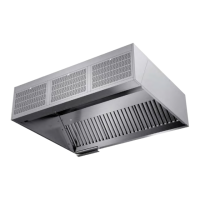
1. Connector for the external controller
2. ModBUS connection point
3. Filter (to be replaced as necessary)
4. Fan (check functionality during maintenance)
5. Electrical supply 230 V LN + protective earth
6.
Climecon CleanMaster controller’s instructions:
The screen also displays the amount of air (l/s)
7. Automation points, see separate instructions:
8.
9.
-
trol device by opening the
NOTE! Remember to take
into account the loose cable
needed for opening the
hatch.
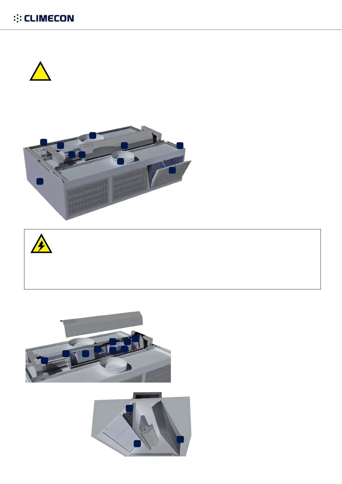
1. Exhaust chamber’s measuring connection
(check the K value from the label inside the hood)
2. UV-approved grease separators
3.
and control air (check the K value from the label inside
the hood)
4. CleanMaster quick guide
CleanMaster features integrated technology for the UV use. A separate control device is not needed. The hood
control device to open. The light has a separate cord that needs to be connected to the lighting group.
1.
2.
3.
4.
5.
6.
7.
8.9.
10.
1.
2.
3. Exhaust air
4. Integrated control device
5. Carrying points M8 in the corners (also in the middle
for the larger size classes, Z iron included to facilitate
mounting)
6. Easily removable supply air slats for maintenance
7. Supply air
8.
9.
10.
Danger of electric shock!
Electricity supply to the control device
NOTE! Electrical connections may only be made by a professional electrician.
- The light is connected to the light group (connection cable as factory equipment)
Always switch the system o before performing any maintenance!
2.
3.
4.
5.
6.
7.
8.
9.
1.
The control device’s hatch can be opened by
3.
2.
1.
OFF
 Loading...