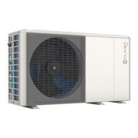
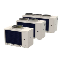
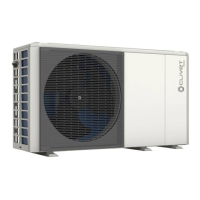
51
Electrical connections
Ref. Description
1 Solar kit signal cable
2 User interface cable
3 Room thermostat cable
4 Boiler control cable
5 Thermistor cable for Tw2
9 Domestic hot water pump control cable
10 2-way valve control cable
10 11 23 3-way valve control cable
12 Thermistor cable T5
13 Booster heater control cable
14 Contactor power supply for domestic hot water storage tank electric heater.
15 Unit power cable
16 Backup heater power cable
17 Solar pump power supply
18 Mixed zone booster power supply
19 Zone 1 (unmixed) booster pump power supply
20 Domestic hot water circulation pump power supply
21 Backup heater consent signal
22 Backup heater temperature reading probe
O
WARNING
All cables are connected to high-voltage lines with the exception of the thermistor cable and user interface
cable.
• The appliance must be earthed.
• All external high-voltage loads, if connected to a metal socket or earthed port, must be earthed.
• The current required for each external load must be less than 0.2 A. If the current required for a single
load is greater than 0.2 A, insert a contactor for control.
• As an example, the ports on terminals “AHS1” “AHS2”, “A1” “A2”, “R1” “R1” and “DTF1” “DTF2” only provide
the switching signal.
• Refer to “7.5.3 Connection terminal block” on page 58 for the location of the ports in the unit.
 Loading...