54
Electrical connections
7.4.3 Sizes 9.1 to 14.1
1
4
5
2
3 6 7
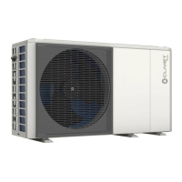
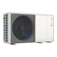
Fig. 46
w
1 Hole for high voltage cable (power supply)
2 Hole for low voltage cable (control and signal cables)
3 Hole for high/low voltage cable
4 Water outlet
5 Water inlet
6 Hole for drain pipe
7 Hole for pressure relief valve drain pipe
L
NOTE
Most of the electrical connections to be done on site are to be performed on the terminal block inside the
control box. To access the terminal block, remove the service panel from the control box and wait 10 min-
utes for the DC bus condensers of the compressor’s inverter to discharge.
W
CAUTION DANGER
Before removing the service panel from the control box, disconnect the power supply to the unit, the back-
up heater, the domestic hot water storage tank and all the other electrically powered components.
O
WARNING
– Secure cables with cable ties
– The external backup heater requires a dedicated electric circuit.
– Installations with domestic hot water storage tank (available as an option) and external backup heater
require a dedicated electric circuit for the booster heater. Refer to the use and installation manual of the
domestic hot water storage tank. Secure the electric cables in the order shown below.
– Lay the electric cables so that the front panel does not lift up during connections and fix the front panel
firmly when finished.
– Connect as shown in the wiring diagrams
– Install the wires and fix the panel firmly so that it fits properly.

 Loading...


