M0G940E8-00 04/07/08 pag 22
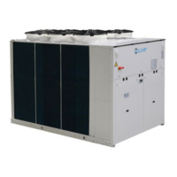
PARAMETERS INDICATIVE VALUES
T EXT
P 12
P 13
SET POINT
40 °C
37 °C
P 175
P 74 P 160
A
B
T EXT
15°C
7 °C
SET POINT
40 °C
37 °C
35 °C
-2 °C-15 °C
A
B
par Description Meaning value
12 CextMaxH Ext. Temp. max. winter correction 15
13 CextMinH Ext. Temp. min. winter correction 0
73 EnLimiteTExtH
Enable corr. SP Heat for external air limit
0
74 TlimiteMaxH
Outside temperature for max SP Heat
-5
115 CompExtH2OS
Enable comp. for External Temp. of the sanitary hot water set point 0
116 MaxCompH2OS
Maximum outside T correction for sanitary hot water set point 10
152 TextEn EXT. Air probe presence 1=YES, 0=NO
160 TlimiteMinH
Outside temperature for min SP Heat
-15
175 MinSetLimiteH
Minimum value that can be set for SP Heat
35
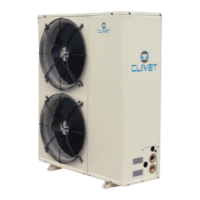
8. DUAL CONTROLS FOR TEMPERATURE – RADIANT PANELS
It is necessary the expansion plug-in module that must be fitted by the client (r refer to the kit instructions) and enabled by
parameter 140 = 1.
With the optional kit, the mixed elements can be controlled: fan coils + radiant panels:
• Radiant panel circulator
• Mixing valve (0-10 volt or ON-OFF)
• Delivery probe (NTC type, 10 Kohm at 25°C)
• External control: COOLING/HEATING LIMIT (avoids dew / overheating).
ATTENTION: to prevent dew in summer or superheating in winter, it is very important to fit an external device and interface it
with the unit that in case of signalling will force the recycling valve on the radiant panels
BLEEDING BY CHILLER RADIANTS IN RECYCLING
8
7°
12°
18°
23°
8
7°
12°
18°
23°
Output status on the optional plug-in module
valv 0-10 10 volt valv 0-10 0 volt
out 22-23 = ON out 22-23 = OFF
3-point valve
out 22-25 = OFF
3-point valve
out 22-25 = ON
The water set point at the radiant panels can be managed in three ways:
1. the valve is managed to maintain the outlet temperature at par 192 value, independently of the unit operating mode
(COOLING or HEATING).
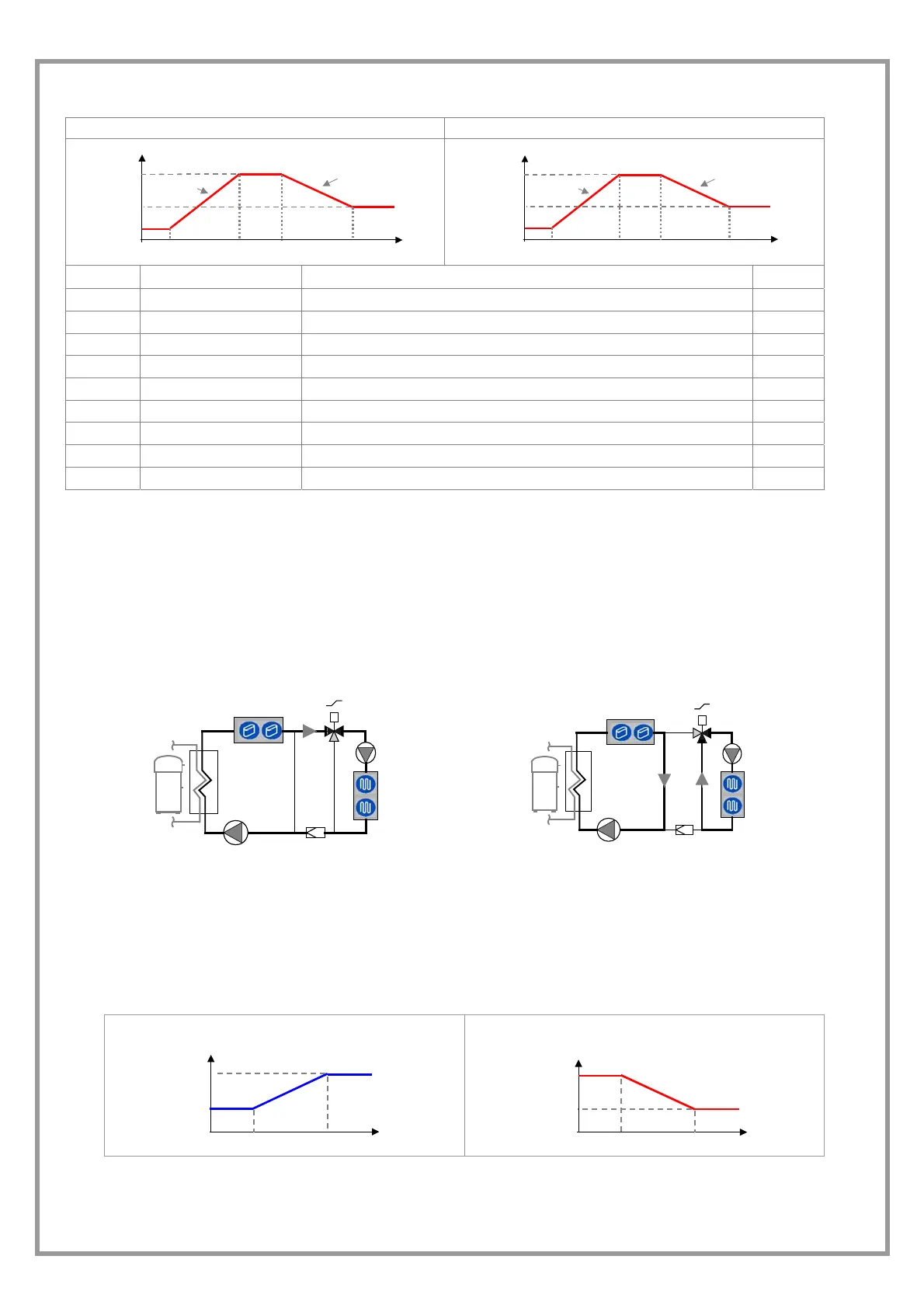
2. calculated automatically in function of the external air temperature; two set are calculated (HEAT. / COOL.) that become
actives on the basis of the unit operating mode. This configuration is obtained setting par 190=1
COOLING HEATING
P 197
P 196
SET POINT
T EXT
P 195
P 194
T EXT
P 201
P 200
SET POINT
P 199
P 198
3. the installation maintains the summer set point at a value higher than the critical one, to avoid the dew formation on the
floor. The unit can be connected via MODBUS to an external device (for example ELFOCONTROL) that transmits the
temperature values and the ambient humidity. This configuration is obtained setting par 191 = 1.
 Loading...