M0G940E8-00 04/07/08 pag 54
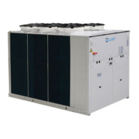
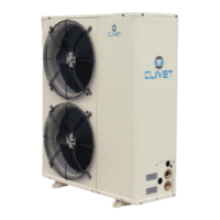
Application: Unit for underfloor heating
Size 21 31 41 51
COOLING
Cooling capacity (23/18°C - 35°C) 1 kW 7,37 8,6 11,9 15,6
Compressor power input (23/18°C - 35°C) 1 kW 1,78 2,17 2,97 4,04
Total power input 2 kW 1,95 2,36 3,27 4,46
EER (23/18°C - 35°C) EUROVENT 3 3,77 3,65 3,64 3,49
EER (EN 14511:2004; 23/18°C - 35°C) 3,48 3,42 3,46 3,4
ESEER 4,48 4,34 4,35 4,05
HEATING
Heat output (30/35°C - 7 °C D.B. / 6°C W.B.) 4 kW 6,72 7,89 10,4 13,6
Compressor power input (30/35°C-7°C D.B. / 6°C W.B.) 4 kW 1,36 1,62 2,18 2,75
Total power input 2 kW 1,6 1,88 2,48 3,22
COP (30/35°C - 7 °C D.B. / 6°C W.B.) EUROVENT 5 4,2 4,2 4,2 4,22
COP (EN 14511:2004; 30/35°C - 7 °C D.B. / 6°C W.B.) 6 4,04 4,02 4,03 4,13
COMPRESSOR
Type of compressors 7 SCROLL SCROLL SCROLL SCROLL
No. of Compressors Nr 1 1 1 1
Std Capacity control steps Nr 1 1 1 1
Oil charge (C1) l 1,1 1,25 1,25 1,95
Refrigerant charge (C1) kg 2,9 5,2 5,4 5,7
Refrigerant circuits Nr 1 1 1 1
INTERNAL EXCHANGER
Type of internal exchanger 8 PHE PHE PHE PHE
No. of internal exchangers Nr 1 1 1 1
Water flow rate (Internal Exchanger) (12/7°C - 35°C) 1 l/s 0,35 0,41 0,57 0,74
Useful pump discharge head (12/7°C - 35°C) 1 kPa 46 70 41 69
EXTERNAL SECTION FANS
Type of fans 9 AX AX AX AX
Number of fans Nr 2 2 2 3
Standard air flow 1 l/s 1014 1030 1270 1764
Installed unit power kW 0,09 0,09 0,115 0,12
CONNECTIONS
Water fittings 1" GAS 1" GAS 1" GAS 1" GAS
HYDRAULIC CIRCUIT
Max water side pressure kPa 550 550 550 550
Safety valve calibration kPa 600 600 600 600
EXPANSION VESSEL
Expansion vessel capacity l 1 2 2 2
No. of expansion vessels Nr 1 1 1 1
POWER SUPPLY
Standard power supply V 400/3/50+N 400/3/50+N 400/3/50+N 400/3/50+N
NOISE LEVELS
Sound pressure level (1 m) dB(A) 55 55 56 59
DIMENSIONS
Length mm 800 800 800 800
Depth mm 300 300 300 300
Height mm 930 1244 1244 1370
Packing volume m3 0,4 0,5 0,5 0,5
(1) data referred to the following conditions :
internal exchanger water = 23/18°C
external exchanger air intake 35°C
(2) Total input is obtained from compressor input
+ fan input
(3) EER calculated as the relationship between
cooling capacity and total absorbed power.
(4) data referred to the following conditions :
water to internal exchanger 30/35°C
External air temperature : 7°C D.B./6.0°C W.B.
(5) COP calculated as the relationship between
heating capacity and total absorbed power.
(6) The indicated COPvalues were calculated
in compliance with the provisions of standard
EN 14511:2004.
(7) SCROLL = scroll compressor
(8) PHE = plates
(9) AX = axial-flow fan
 Loading...