Z4-8MK4 Installation and User Guide v1.210
INSTALLATION
Hardware Considerations
The Z8MK4 and Z4MK4 Zone Mixers are built in 3U-high 19”
rack mount enclosures. It is recommended that the Zone
Mixer is installed in a 19” rack wherever possible. The units
are approx. 160 mm deep, but 250 mm of rack depth should
be available to allow for rear connectors and cabling.
The Z8MK4 and Z4MK4 have low power consumption and
there are no thermal considerations other than ensuring that
the ventilation grilles are not obstructed once the mixer is
installed. The ventilation grilles are at the rear (immediately
above the AC input connector); in the bottom panel (behind
the AC mains switch), and in the left-hand side panel. Other
equipment may be installed above or below the Z8MK4/Z4MK4
within this constraint.
The choice of location will be dictated by the specics of
the system and building layout. It is recommended that
wherever possible, the Z8MK4/Z4MK4 should be mounted in
an equipment rack along with as many of the music sources
(CD players, music servers, TV receiver boxes, etc.) and audio
power ampliers (driving the zone loudspeakers) as practical.
When deciding the Zone Mixer’s location, bear in mind that
access to it will probably be required even if a full complement
of remote controls is being tted as part of the system, as
some adjustments can only be made on the mixer itself.
Power Supply
The Z8MK4 and Z4MK4 are tted with a Universal power
supply which can operate on mains voltages from 85 to 253 V.
An IEC mains cable with a plug appropriate for your country is
supplied. The units’ power consumptions are 10.6 W (Z8MK4)
and 6.5 W (Z4MK4), with no accessories connected.
Fuses and ratings
The only user-accessible fuse is an AC mains fuse in the IEC
connector housing. Only replace a fuse with one of
exactly the same type. The fuse rating is 1 A; the type is a
T1A, size 20 x 5 mm, with high breaking capacity.
The fuseholder may be accessed by prising the cover below
the connector open, using a small screwdriver. The holder has
an extra cavity for storing a spare fuse; note that the “active”
fuse is that in the inner cavity.
System Connections
Music Sources
Connect the system’s various music sources to LINE 1 to
LINE 6. Line Inputs 1 and 2 are unbalanced, on standard RCA
jacks (phono sockets), while Line Inputs 3 to 6 are balanced,
on 3-pin 3.5 mm-pitch screw-terminal connectors. All six
inputs are stereo, with separate L and R connectors. The
sensitivity range available should allow most standard items
of audio equipment such as computers/tablets, music servers
and media receivers, etc., to operate at a satisfactory level.
Unbalanced sources:
Source equipment with stereo unbalanced outputs may be
connected directly to Line Inputs 1 or 2, and as long as the
source is adjacent to the Zone Mixer, normal phono-phono
(or 3.5 mm jack-to-phono leads) can be used. Always avoid
using pre-made leads of an unnecessary length.
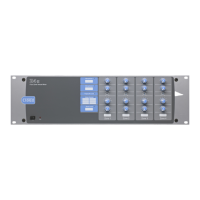
If it is necessary to connect an item of source equipment with
a balanced output to Line Inputs 1 or 2, the ideal method
is to use a balancing transformer between the source and
the unbalanced input. Suitable audio transformers, which
should have a ratio of 1:1, are readily available from major
audio component suppliers. The transformer(s) should be
mounted as close to the Zone Mixer as practical, and housed
in a screened enclosure if they are not individually screened.
The preferred connection method is shown below.
LEFT
+
-
SCN
Unbalanced
inputs
SCN
LEFT
+
-
SCN
Audio balancing transformers
RIGHT
+
-
SCN
Unbalanced
inputs
SCN
+
-
n1ground
n2hot
n3cold
12
3
12
3
If transformers are not available, a balanced source may feed
an unbalanced input directly as long as care is taken over how
the connections are made. A variety of design techniques are
in use to implement balanced outputs in audio equipment,
and some designs require different wiring protocols to others.
Installers are advised to check the manuals with each item
for guidance on how the outputs should be connected to an
unbalanced input.