Z4-8MK4 Installation and User Guide v1.2 13
Before the LM-2’s music source and level controls will
operate, set the MUSIC CONTROL push-button switch
([17] on page 9) for the Zone where the LM-2 is installed
to REMOTE (i.e., pressing it in). In this setting, the Zone’s
front panel Music Source and Music Level controls
become inoperative.
Sometimes it is desirable to permit remote control of music
level but keep music source selectable only on the mixer. In
this case, internal jumper J1 on the sub-board for the Zone in
use should be moved from ‘SW’ to ‘FR’. This will render the
LM-2’s music source switch inoperative, and return source
selection to the front panel. See page 26 for full details and
jumper locations.
Paging System connections
Cloud PM Series paging microphones may be connected
directly to the Z8MK4 and Z4MK4. All models except the
PM1 can use either the Cloud Digital Paging Interface or an
industry-standard analogue interface; Model PM1 uses the
analogue interface.
PM microphones are available in 4, 8, 12 or 16-zone versions;
the installer should be sure he/she understands how paging
zones correspond to mixer zones before commencing wiring.
Connecting a PM4/4SA/8/8SA/12/16 paging mic via
the Cloud Digital Paging Interface
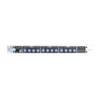
The Z8MK4 and Z4MK4 are tted with a Cloud Digital Paging
Interface; this uses two RJ45 sockets: IN and THRU. Cloud
PM Series Paging microphones may be connected directly to
the IN socket with Cat 5 cable; the single connection provides
all audio, control and power required by the microphone.
The IN port is able to supply 350 mA to power paging
microphones. This is adequate to power one or two
microphones of models PM-4, PM-8, PM-12 or PM-16. Cloud
recommend that all ‘-SA’ models (with spot announcement
sound stores) are powered by a separate, external PSU, as
described in the PM Series Installation Guide. (A suitable
PSU is supplied as standard with all ‘-SA’ models.) Note
that the THRU port is not able to supply DC power, and
is not intended for the connection of additional PM Series
microphones (see below).
Connect the OUT socket of the PM Series microphone
to the IN socket on the Zone Mixer with Cat 5 cable. The
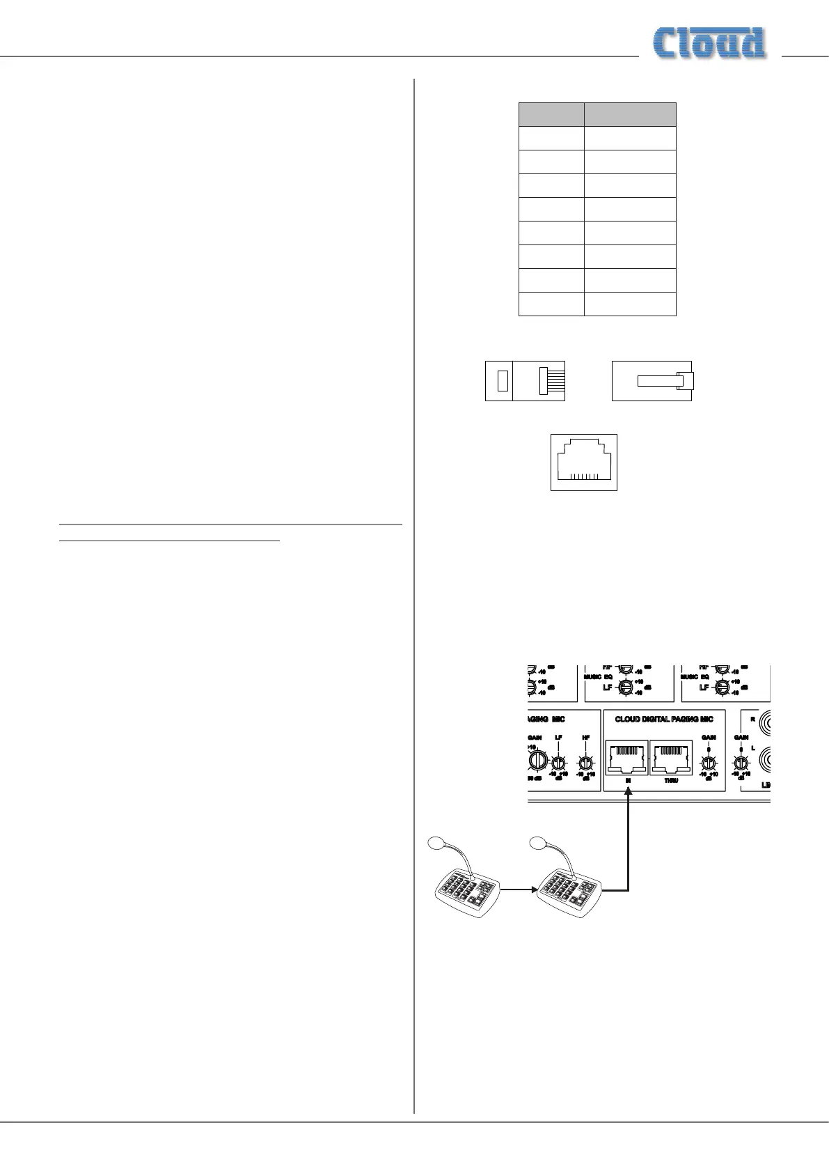
standard Cat 5/RJ45 wiring convention is shown opposite.
RJ45 PIN CAT5
1 Brown + White
2 White + Brown
3 Green + White
4 White + Blue
5 Blue + White
6 White + Green
7 Orange + White
8 White + Orange
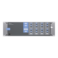
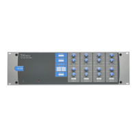
5-3/8*3,16,'( 5-3/8*/$7&+6,'(
5-62&.(7
The Cloud Digital Paging Interface allows multiple PM Series
microphones to be “daisy-chained”. If more than one paging
microphone is being installed – typically at different locations
in the building, connect the OUT socket of one to the IN
socket of the next.
INOUT OUT
The THRU connector allows two or more Z8MK4/Z4MK4
mixers to be interconnected: for example, a PM16 paging
microphone can address all sixteen zones it can support
through the use of two Z8MK4 mixers. If the THRU socket is
in use, the Interface termination will need to be disabled; this
is done by moving an internal DIP switch; see “PCB jumper
location and settings” on page 26 for details.