Z4-8MK4 Installation and User Guide v1.2 21
OPTIONS AND ADDITIONAL INFORMATION
LM-2 active input modules – general considerations
Cloud LM-2 remote input modules are available in various form factors, to t double-gang UK or other back boxes styles. Please
refer to www.cloud.co.uk/accessories for details of the full range. Back boxes of either the recessed type or surface-mounting
type may be used, providing they are at least 35 mm deep.
The modules should be connected to the FACILITY PORT of the relevant zone using screened Cat 5 cable as described
at page 12 . The OUTPUT connector on the module and the FACILITY PORT on the mixer are both screened RJ45
connectors.
Great care must be taken when connecting active input modules; power is derived from the mixer and some wiring errors may
cause failure of the mixer. Please check all wiring before testing the system.
IMPORTANT: Please refer to page 28 for information regarding current draw and power supply capability.
Connecting multiple LM-2s
It may be desirable to connect local microphones or music sources at more than one location in a zone (in a large function
room, for example). LM-2 input modules may be “daisy-chained” using their second LINK RJ45 connectors to achieve this. All
LM-2s thus wired will, of course, only be available to the zone to whose Facility Port the chain is connected.
Remember to consider the current drawn by any additional input plates – see page 26 for details of current consumption
and PSU capability.
See also the section below: “Disabling the Facility Input Noise Gate”.
Using the Facility Ports as auxiliary zone inputs
The Facility Port provides a balanced audio input. If a Facility Port is not connected to an LM-2 remote input module, it may be
used as a direct input to the zone from other equipment forming part of the system (for example, a permanently installed DJ
mixer which only ever needs to feed its output to that particular zone).
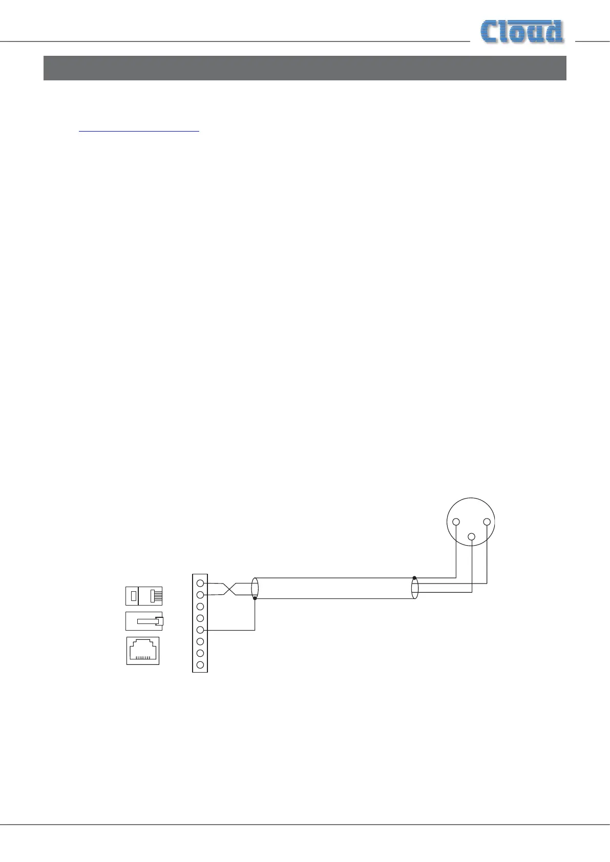
Wire an external balanced source to the facility port as shown below:
1
8
7
6
5
4
3
2
Z4MK4/Z8MK4 FACILITY
PORT (RJ45)
1
3
2
OUTPUT(e.g.
hot (+)
hot (+)
cold (-)
cold (-)
1
8
1
8
1
8
An unbalanced source may also be connected; the use of balancing transformers is recommended.
Disabling the Facility Port Noise Gate
The balanced audio input at the Facility Port is fed through an internal noise gate, to minimise any background noise from
an LM-2 or other source connected to the port. The threshold of the noise gate is xed at a fairly low level, so that use of a
microphone connected to an LM-2 will normally open the gate immediately.
If any problems are experienced with the gate’s operation, it may be disabled by moving jumper J7 on the zone sub-board. When
disabled, even very low-level audio signals from the LM-2 or other external source will be audible.