Z4-8MK4 Installation and User Guide v1.212
Microphone inputs
MICROPHONE 1 and MICROPHONE 2 inputs are
intended for the direct connection of microphones. They are
electronically balanced and transformerless with an input
impedance of greater than 2 kohms and optimised for use
with microphones of 200 to 600 ohms impedance. The screw
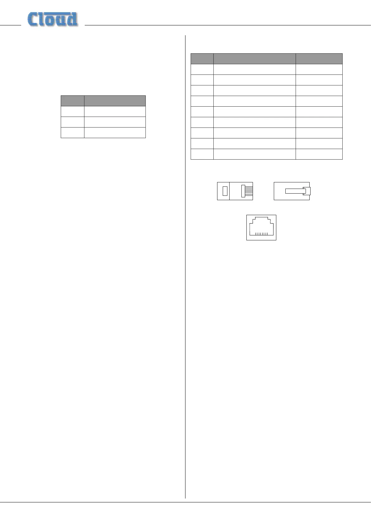
terminal input connectors should be wired thus:
PIN CONNECTION
1 Screen
2 Signal ‘-’ (cold)
3 Signal ‘+’ (hot)
Unbalanced microphones may be used by connecting pin 2
to pin 1 (cable screen) in the mating (male) screw-terminal
connector.
12 V phantom power is available, see “Phantom Power” on
page 17.
Each mic input may be routed to any of the zones in use, at any
level in each zone. Each zone may be congured so that any
microphone announcements automatically reduce the music
level in that zone while the announcement is in progress (see
“Mic 1/Mic 2 priority” on page 19 for more details.)
The PAGING MIC input has the same
electrical characteristics as MICROPHONE 1 and
MICROPHONE 2, but is intended for the connection of
a dedicated paging microphone. Mic signals at this input will
route to all zones at a level determined by the front panel
preset Paging Level controls, ducking the music while
an announcement is in progress. VOX or contact-closure
triggering of the paging priority circuit may be selected; see
“Paging mic priority” on page 19 for more details.
Facility Ports
Each zone of the mixer is provided with a Facility Port in
the form of a rear panel 8-way RJ45 connector. The primary
use of the Facility Port is for the connection of LM-2 remote
active input modules, but it may also be used as a general-
purpose, per-zone auxiliary balanced input (see “Using the
Facility Ports as auxiliary zone inputs” on page 21 for more
information on this application). Note that audio connected
via a Facility Port will only appear at the same-numbered
Zone Output, and no other.
The active modules operate on DC power supplied by the
mixer. The current consumed by each module is minimal and in
the vast majority of installations there will be no power supply
issues. Nevertheless, installers are urged to check the data in
the Appendix regarding PSU capacity (see “PSU capability and
optional device current consumption” on page 28).
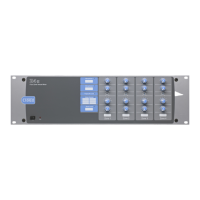
The pinout of the Facility Port connector is given in the table
below:
PIN USE Cat 5 CORE*
1 Audio ‘cold’ phase (-) White + Orange
2 Audio ‘hot’ phase (+) Orange
3 Priority VCA control White + Green
4 + 12 V Blue
5 0 V White + Blue
6 -12 V Green
7 Music level control (0 to 10 V) White + Brown
8 Music source select control (0 to 10 V) Brown
SCN Screen for system music controls Connector shell
* Standard wiring for pre-made cables
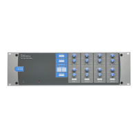
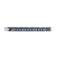
5-3/8*3,16,'( 5-3/8*/$7&+6,'(
5-62&.(7
Please also refer to “LM-2 active input modules – general
considerations” on page 21 for further information
regarding installation of remote active input modules.
Connecting an LM-2 remote input module
The LM-2 should be connected to a Facility Port using
screened Cat 5 cable. (Note that as the cable carries analogue
audio, only screened Cat 5 should be used.) All 8 cores are
used. The LM-2 includes controls for local music level and
source selection, the wiring for these functions being catered
for on the Facility Port. Thus it is not necessary to make any
connections to the Zone’s REMOTE SOURCE+LEVEL
Port.
The LM-2’s upper PCB is tted with an RJ45 connector
labelled OUTPUT. Connect this to the FACILITY PORT
of the relevant Zone using screened Cat 5 cable with screened
RJ45s at each end. Follow the colour coding shown in the
previous table. The metal screening of the connectors should
be bonded to the screen of the cable. Full details can be found
in the LM-2 Installation Guide.
The second RJ45 connector on the LM-2, ‘LINK’, may be used
to “daisy-chain” additional LM-2s, thus allowing multiple input
modules to be installed at different locations in the zone. See
the LM-2 Installation Guide for more details.