Z4-8MK4 Installation and User Guide v1.218
The diagrams below indicate how these rules are applied in
some common wiring schemes.
INOUT
OUT
Z8MK4/Z4MK4
OUT
OUT
Termination ON
Termination ON
Termination OFF
IN
THRU
IN
THRU
Z4MK4
Z8MK4
Termination ON
Termination
ON
Termination ON
Termination OFF
Termination
ON
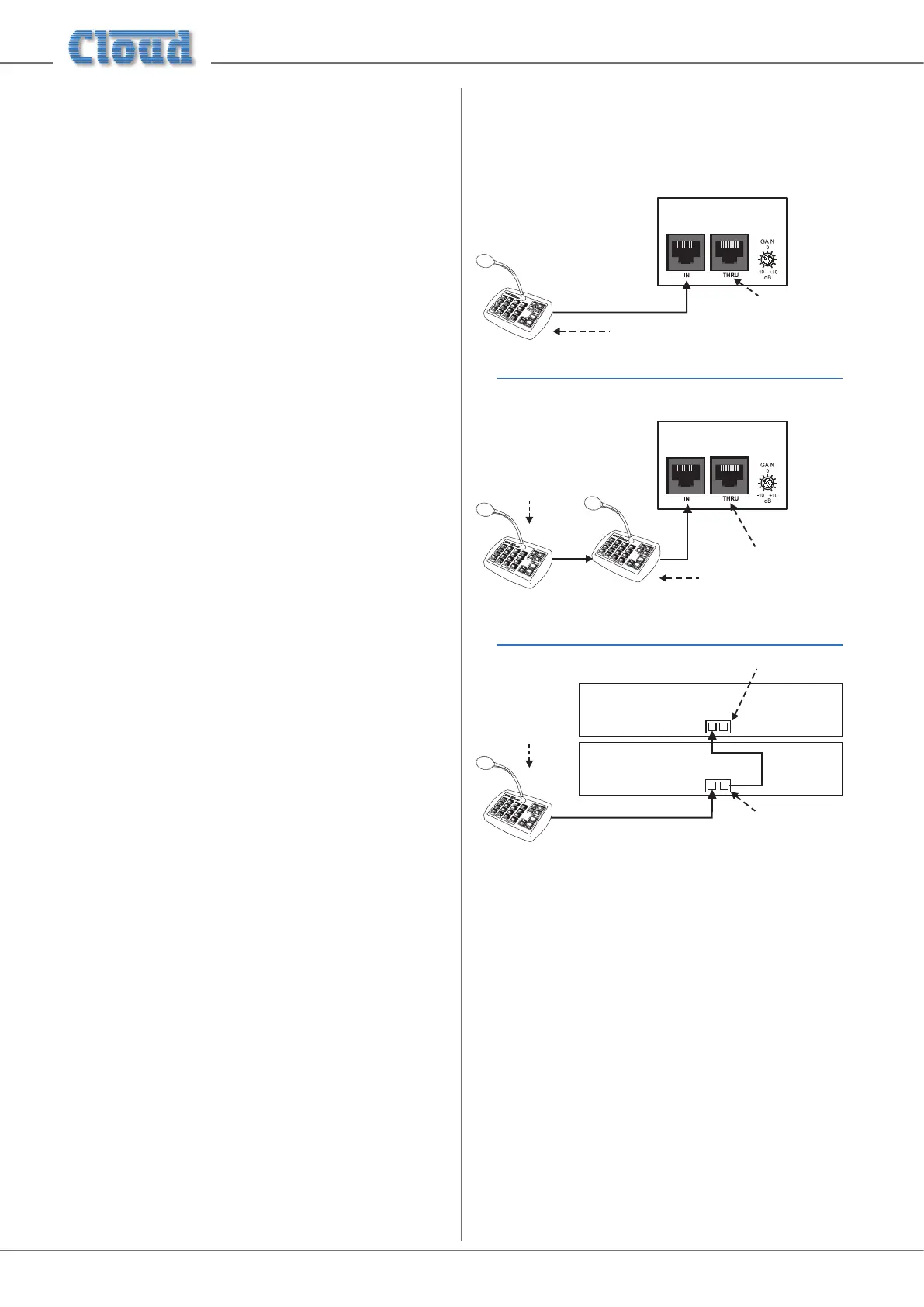
Example 1
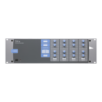
Example 2
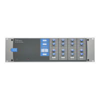
Example 3
CLOUD DIGITAL PAGING MIC
Z8MK4/Z4MK4
CLOUD DIGITAL PAGING MIC
• In the simplest implementation of just one paging
microphone, the terminations should be set ON at both
the Zone Mixer and the microphone.
• If two or more microphones are daisy-chained to the
Zone MIxer’s IN socket, terminations must be ON at
the Mixer and the “end” microphone only.
• If two Zone Mixers are daisy-chained using the IN and
THRU connectors, the terminations at the “ends”
of the chain should be ON. In Example 3 above, this
will be at the paging microphone and Mixer #2. The
termination in Mixer #1 should be set to OFF (as it is in
the “middle” of the chain).
Refer to the PM Setup and Installation Guide (supplied with
each PM paging mic) for information on setting the buss
termination in the microphones.
Paging mic input
Phantom Power
The PAGING MIC input also has 12 V phantom power
available. This will NOT be required if a Cloud paging
microphone is being used with the mixer, but may be necessary
with other manufacturers’ equipment. It is enabled by moving
its section of the internal motherboard DIP switch SW3 to its
ON position. See page 26.
Gain & level
The PAGING MIC input has a rear panel preset gain control
([8] on page 9). A wide range of gain is available and there
should be no problem in obtaining a satisfactory level from
most paging microphones.
The mic GAIN control should be adjusted by making an
announcement. Set the front panel Paging Mic Level preset
control at about halfway and listen in a convenient zone; the
rear panel gain control should be carefully advanced until
the announcement is heard clearly and without distortion.
If possible, the person who will normally make paging
announcements should speak when making this adjustment.
Following the setting of the paging mic gain, the paging level
in all the other zones should be set, by listening in each zone,
with the Paging Mic Level controls on the front panel ([5]
on page 8).
EQ & high-pass lter
The PAGING MIC input has associated HF and LF EQ
controls ([9] on page 9). These are identical to the MIC
1 & MIC 2 EQ controls (see previous page) and should be
adjusted similarly. A 100 Hz xed lter is also included in the
circuitry, as with the other mic inputs.
Cloud Digital Paging Mics
Cloud PM Series Digital Paging Microphones can be connected
directly to the IN connector of the CLOUD DIGITAL
PAGING MIC interface (see [10] at page 9), using a
single Cat 5 cable. For many situations, this will be all that is
required at installation, but there are two factors which may
need to be taken in consideration: network termination and
zone offset.
Network termination
Network termination rules apply to the Cloud Digital Paging
Interface. The Z8MK4/Z4MK4 and one or more PM Series
microphones constitute a network, and buss terminations
should be set ON in the two devices at the “ends” of the
chain, and OFF in all others.
The buss termination in the Zone Mixer is set ON at the
factory, but may be set OFF by moving one section of internal
motherboard DIP switch SW2. Refer to page 26 for
location of motherboard components.