Z4-8MK4 Installation and User Guide v1.2 25
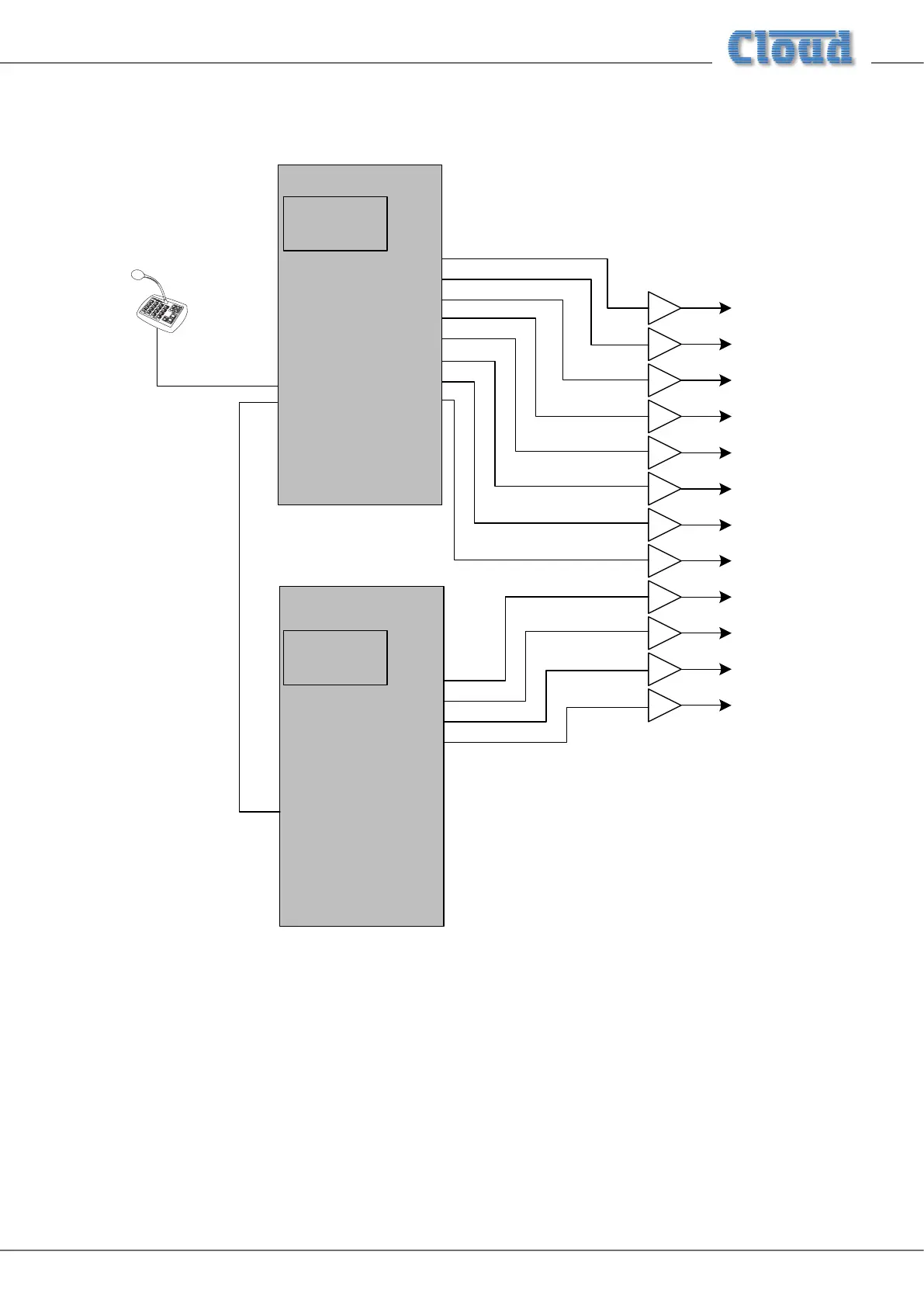
Application example 2
This example shows how two Zone Mixers – in this case one Z8MK4 and one Z4MK4 – can be used in conjunction with the
Cloud Digital Paging Interface to allow a PM12 Paging Microphone to correctly address all 12 zones.
ZONE 5
ZONE 3
ZONE 2
ZONE 6
ZONE 8
ZONE 4
ZONE 7
ZONE 1
OUTPUTS
DIGITAL PAGING
INTERFACE
IN
THRU
PM12
ZONE 3
ZONE 2
ZONE 4
ZONE 1
OUTPUTS
DIGITAL PAGING
INTERFACE
IN
THRU
Z8MK4
Z4MK4
SW2 settings:
Termination: OFF
Zone Offset: 0
SW2 settings:
Termination: ON
Zone Offset: 8
ZONE 5
ZONE 3
ZONE 2
ZONE 6
ZONE 8
ZONE 4
ZONE 7
ZONE 1
ZONE 11
ZONE 10
ZONE 12
ZONE 9
The Digital Paging Interface THRU port of the Z8MK4 is connected to the IN port of the Z4MK4 using Cat 5 cabling. The
important points to note are:
• The buss termination should be set OFF in the Z8MK4, as it is not at the “end” of the network chain. However, the
termination in the Z4MK4 should be set ON.
• Zone Offset should be set to 8 in the Z4MK4 (and left at zero in the Z8MK4). This will allow zone buttons 9 to 12 on the
PM12 to correctly address the four zones driven by the four-channel Zone Mixer.
• The diagram only shows the Digital Paging Interface and output connections for simplicity. In practice, all music sources
and microphone inputs would need to be paralleled to both Zone Mixers. Direct parallel connection will probably prove
satisfactory for the line inputs, but the use of a two-way passive or active mic splitter is recommended for use with the
microphone inputs.