C.M.C. n.v. - Airmaster S1 installation guide – V1.2 – MANY0402A.00
6.4 Digital inputs
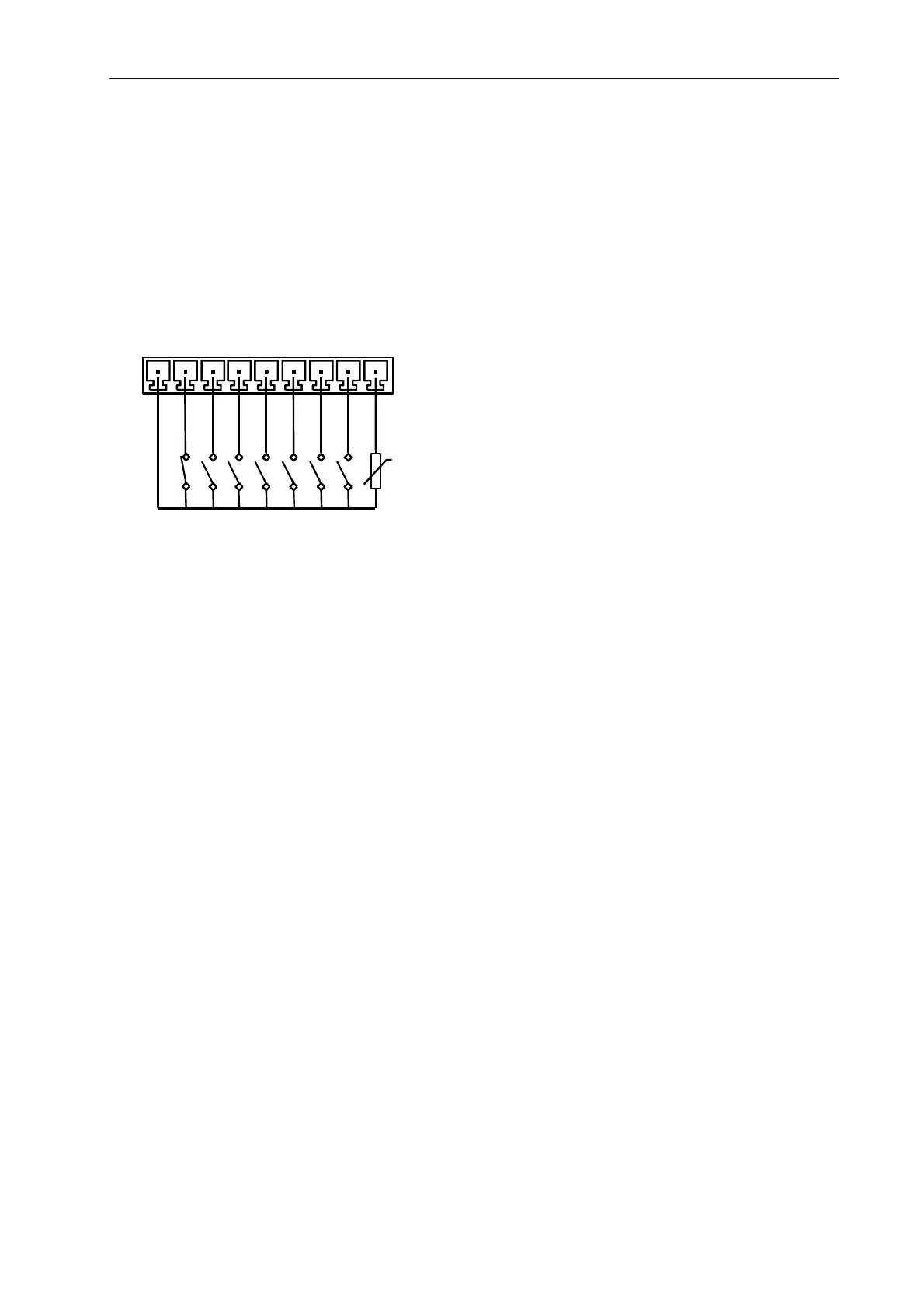
There are 8 digital inputs on the S1 unit: 1 for the emergency stop button, 6 general
purpose and 1 PTC input.
Connector X04
PTC1
1
9
X04
C+
ES
C1
C
C3
C4 C5
C6
C7
C8
pin 1 C+ Common
pin 2 C1 Input 1
pin 3 C2 Input 2
pin 4 C3 Input 3
pin 5 C4 Input 4
pin 6 C5 Input 5
pin 7 C6 Input 6
pin 8 C7 Input 7
pin 9 C8 Input 8
Common Terminal
Voltage 24VDC
Sink Current up to 200mA
Digital Input 1 (Emergency Stop)
Sink Current 10mA max
Resistance closed contact < 3 ohm
Resistance open contact > 750 Kohm
Digital Inputs 2 to 7 (general purpose)
Sink Current 10mA max
Resistance closed contact < 13 Kohm
Resistance open contact > 750 Kohm
Digital Input 8 (PTC thermistor)
Sink Current 1.4mA
Resistance closed contact < 750 ohm
Resistance open contact > 4000 ohm
Conformity IEC 34-11-2, VDE 0660
Note: all resistance are inclusive the resistance of the cabling.
Page 17 of 35
 Loading...