C.M.C. n.v. - Airmaster S1 installation guide – V1.2 – MANY0402A.00
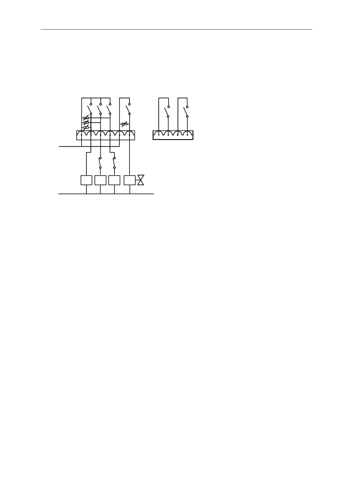
6.5 Relay outputs
The Airmaster S1 has 6 relays.
X03
R1
R2
R3
R4
R5
EXAMPLE
R6
K1
K2 K3
S1
1
4
+VC
0VC
6
1
OPTIONAL
X02
Switching Voltage (max) 240Vac / 24Vdc
Continuous Current (max) 8Aac / 8Adc (resistive load) (*)
Breaking Capacity (max) 1800VA (cosØ=1) / 150W dc
Switching Rate 300 ops/min (no load)
30 ops/min. (rated load)
Mechanical Life 10M ops
Contact Life @ load 100K ops (cosØ=1)
Operating Time 10ms max
Release Time 10ms max
VDR Rating (R1 to 4) 300Vac / 385Vdc
Maximum current pin 1 12Aac or dc (15A peak for <3s)
for UL: 10A @ max. 240Vac
(*) See Appendix 3 for UL508 ratings.
Connector X03 pin 1 C-R1,2,3 R1,2 and 3 common
pin 2 NO-R1 R1 normally open
pin 3 NO-R2 R2 normally open
pin 4 NO-R3 R3 normally open
pin 5 NO-R4 R4 normally open
pin 6 C-R4 R4 common
Connector X02 (optional)
pin 1 NO-R5 R5 normally open
pin 2 C-R5 R5 common
pin 3 NO-R6 R6 normally open
pin 4 C-R6 R6 common
Page 19 of 35
 Loading...