USER’S M A NUA L
16
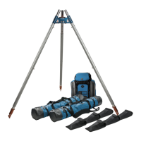
Easel Tripod (raptor feet)
10’
8’
5F04
MEETS THE PORTABLE ANCHOR REQUIREMENTS OF NFPA 1983,
STANDARD ON LIFE SAFETY ROPE AND EQUIPMENT FOR EMERGENCY SERVICES, 2017
EDITION.
EMERGENCY SERVICES PORTABLE ANCHOR IN ACCORDANCE WITH NFPA 1983, 2017
EDITION.
MINIMUM BREAKING STRENGTH AND RATING ARE DETERMINED AT THE
CONFIGURATION OF LOWEST STRENGTH PER MANUFACTURER’S INSTRUCTIONS.
RATED G (GENERAL USE), MBS 36 kN FOR THE FOLLOWING CONFIGURATIONS:
VORTEX NFPA CERTIFIED CONFIGURATIONS
CONFIGURATION 1 Tripod (all legs equal
length)
1. 2 outer legs coupled to 1 inner leg at maximum
length (9 ft / 2.7 m)
2. Head unit connected to the inner leg via upper
head pin hole and last inner leg pin hole
3. Use either Raptor or Flat Feet
4. Legs at equal distance apart
5. Feet are required to be individually hobbled
or anchored
CONFIGURATION 2 Easel A-Frame
1. A-FRAME SECTION 2 outer legs coupled to1
inner leg at maximum length (8 ft / 2.4 m)
2. EASEL LEG SECTION 3 outer legs coupled to1
inner leg at maximum length (10 ft / 3.0 m)
3. A-frame head unit connected to the inner leg via
upper head pin hole and
third
to last outer leg
pin hole
4. Easel head unit connected to the inner easel leg
via third-to-last leg pin hole
5. A-frame section must be at 90 degrees relative to
the surface
6. Use either Raptor or Flat Feet
7. Easel leg to A-frame leg distance 10 ft (3 m)
8. Feet are required to be individually hobbled
or anchored
GENERAL WARNINGS
• These instructions DO NOT inform you of every possible
hazard and every conceivable risk relating to the use of this
equipment.
• The environment where this equipment can be used may
be inherently dangerous. Activities performed within
these environments carry a high risk of injury and death.
Although proper training and experience may reduce this
risk, ultimately the risk cannot be eliminated.
• Do not use this equipment unless you fully understand and
assume all risks and responsibilities for all damage / injury
/ death that may result from use of this equipment or the
activities undertaken with it.
• The Vortex is intended for use by medically t, specically
trained and experienced users.
• All users of this equipment must obtain and thoroughly
understand the user instructions and refer to them before
each use.
• Any time a person is suspended by a rope based system,
a secondary system should be in place in case of a
component failure. You must always have a backup. Never
trust your life to a single tool or component.
• The user must have a rescue plan and the means to
implement it. Inert suspension in a harness can quickly
result in death!
• Do not use around electrical hazards, moving machinery,
or near sharp edges or abrasive surfaces.
• Do not exceed the limits of the equipment.
• Verify compatibility with other components of your
system. Incompatible connections can cause detachment,
breakage, etc.
• CMC is not responsible for any direct, indirect or accidental
consequences or damage resulting from the use or misuse
of this product.
• The user must stay up to date! Regularly access the CMC
website and read the latest advice and user instructions.
• Please note that some diagrams in this manual have
omitted guy lines and hobble straps for clarity. Guy lines
and other methods for properly securing and supporting
the Vortex are essential for safe operation and use.
VORTEX SPECIFIC WARNINGS
• The Vortex is not like a standard tripod. The user must have
a greater level of knowledge and understanding to secure
and stabilize the Vortex.
• The Vortex head and feet must be secured to resist all
movement.
• The Vortex should, whenever possible, be constructed
away from the edge. Prior to moving it into position the
supplied Tether Cord should be attached to the head of
the assembly and congured as a belay while the Vortex is
being moved and secured into position.
• The head hinge joint and the Flat Foot ball joint loaded to
their rotational limits can create a leverage aect that may
damage components.
• The ball joints of the Flat Feet are not designed to with-
stand tensile forces. The leg, and/or the head, must be
secured to ensure these are not subjected to tensile forces.
• All legs must be fully inserted into, or extend beyond the
A-Frame head.
• The edges of the A-Frame Pulley Wheel are not fully en-
closed. To avoid damaging the rope or adding unwanted
friction to the system, it is essential that the rope running
into and out of the Pulley Wheel is correctly aligned.
• Do not couple more than four (4) leg sections (three Outer
plus one Inner Leg) together on any one leg.
• Check the ball-lock pins after insertion to ensure they are
completely inserted and the locking balls are fully extend-
ed and locked.
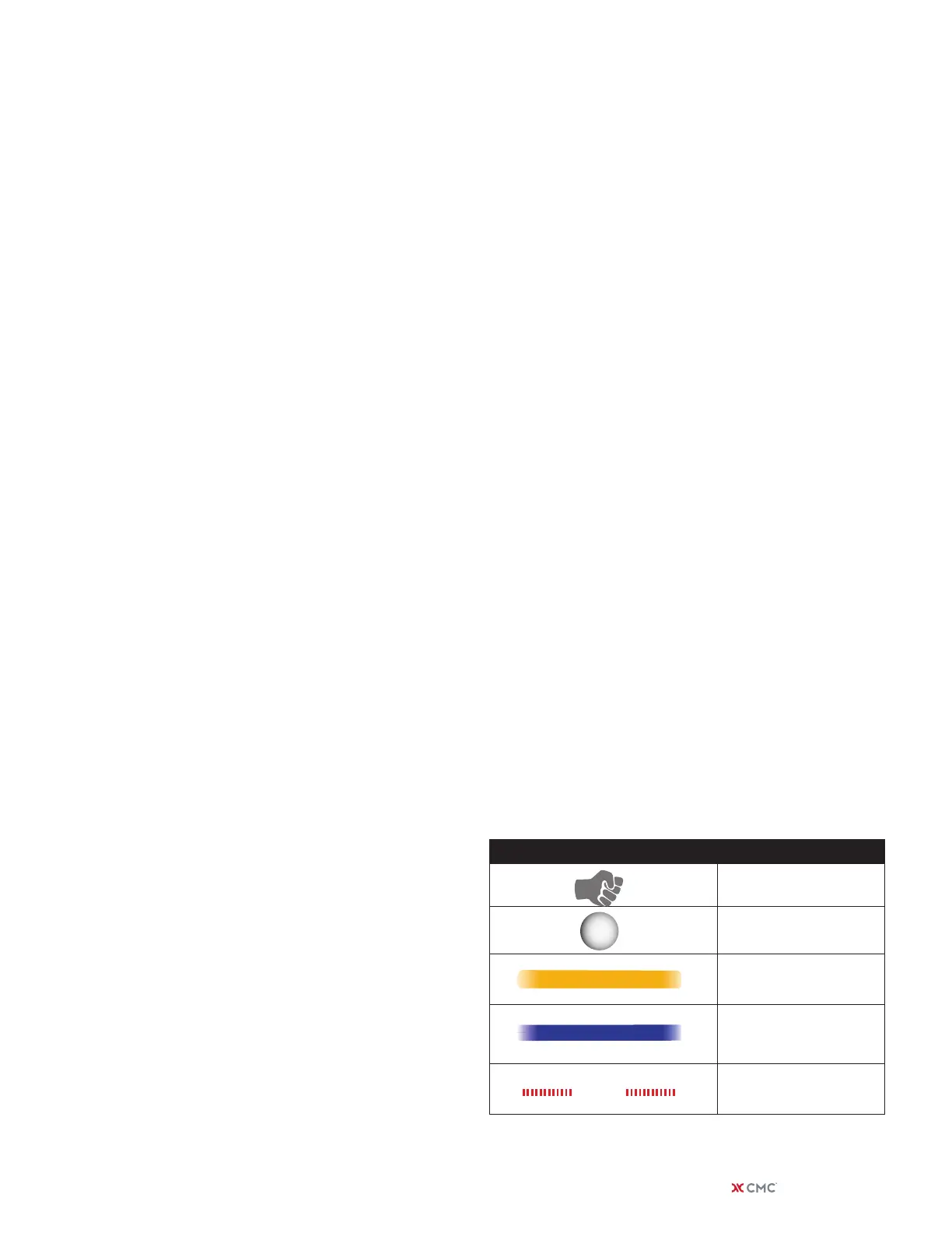
SYMBOL MEANING
Haul line
Mass of payload
Straps preventing feet
from spreading apart
Line preventing the
Vortex from toppling
Total force acting on
frame
HOBBLE STRAP
GUYLINE
APPLIED
FORCE
LOAD
DIAGRAM LEGEND
| cmcpro.com 5
 Loading...