Do you have a question about the CMC ARIZONA VORTEX KIT and is the answer not in the manual?
Maximum service life of Vortex metal products is undefined, lifespan reduced by use, environment, misuse, storage.
Detailed periodic inspection by competent person every 12 months; frequent checks for use and environment.
Record of inspections should be kept and made available per laws and policies.
Wash components after use, dry, store in clean dry place away from heat and chemicals.
Details assembly steps for a tripod configuration with equal leg lengths.
Details assembly steps for an easel A-frame configuration with specific leg lengths.
Key technical specifications including clearance, height, weight, and pin strength.
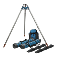
Lists all parts included in the Arizona Vortex Kit.
Details the components included in the carrying bag set.
Details outer legs, inner legs, leg/foot pins, and head pins.
Describes A-Frame Head, Gin Pole Head, Raptor Feet, and Flat Feet.
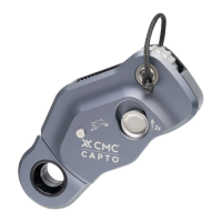
Describes the Pulley Wheel component and its attachment.
Illustrates how the A-Frame and Gin Pole Heads are pinned together for tripod assembly.
Details the step-by-step assembly process for an Easel-Leg Tripod configuration.
Explains how the A-Frame Head can construct bipod configurations like Classic A-Frame or Sideways A-Frame.
Describes the use of the Gin Pole Head for monopods or coupling with A-Frame for tripods.
Instructions for aligning the Gin Pole Head and A-Frame Head at connection points.
Explains how the Gin Pole Head angle can be adjusted relative to the A-Frame Legs.
Shows how to connect Outer Legs to both the Gin Pole and A-Frame Heads.
Illustrates the process of connecting Inner Legs to the Gin Pole and A-Frame Heads.
Explains the correct assembly of Outer and Inner Legs using the Leg Pin.
Details correct placement of pin balls to secure the pin in place.
Explains the correct connection of two Outer Legs using the alignment stud and ball-lock pin.
Guides on setting the Flat Foot ball joint to avoid articulation limits.
Advises on positioning the Raptor Foot for optimal grip.
Overviews of Tripod and Easel-Leg Tripod (Winch) as Anchor Frames.
Overviews of A-Frame, Sideways A-Frame, Easel-Leg Tripod (Pulley), and Gin Pole as Directional Frames.
CMC recommendations, identifying usage mode and applied force.
Assessing movement tendencies and securing feet and head.
Guidelines for guy angles and procedures for test loading the rigging.
Explains the two primary Modes of Use for the Vortex.
How to determine applied force for Anchor Frame mode.
How to determine applied force for Directional Frame mode.
Explains foot movement tendencies for Equal Leg Tripod and importance of hobbles.
Describes how haul line positioning affects frame movement tendency.
Illustrates force tendencies for Easel-Leg Tripod (Winch) in Anchor Frame mode.
Illustrates force tendencies for Easel-Leg Tripod (Pulley) in Directional Frame mode.
Details methods for securing the Vortex feet to resist all forms of movement.
Explains how to secure the Vortex head to resist movement tendencies.
Lists recommended criteria for selecting additional guying material.
Provides rules of thumb for Guy Angle and Applied Force Angle for force calculation.
Illustrates Guy Angles on an Anchor Frame configuration (Gin Pole).
Illustrates Guy Angles on a Directional Frame configuration (Gin Pole).
Defines the Guy Plane as the plane formed by guylines.
Defines the Frame Plane as the plane formed by Vortex legs.
Requirements for support structures when used as an Anchor Frame.
Requirements for support structures when used as a Directional Frame.
Introduces the following pages detailing common Vortex configurations.
Guide for visual, tactile, and functional inspection of parts before and after each use.
Specific inspection points for Vortex pins and the headset pulley.
Instructions for removing the Vortex from service if any component fails inspection.
| Brand | CMC |
|---|---|
| Model | ARIZONA VORTEX KIT |
| Category | Safety Equipment |
| Language | English |