APPLIED
FORCE
APPLIED
FORCE
Fig. 3e
When the load is applied, the force
acting on the Directional Frame will
cause a rearward tendency of move-
ment. The front legs of the Easel-Leg
Tripod will have a tendency to spread
apart, while the rear leg will have a
tendency to move backwards.
Directional Frame
MODE OF USE:
CONFIGURATION:
Easel-Leg Tripod
(w/directional pulley)
Anchor Frame
MODE OF USE:
CONFIGURATION:
Easel-Leg Tripod
(w/leg-mounted winch)
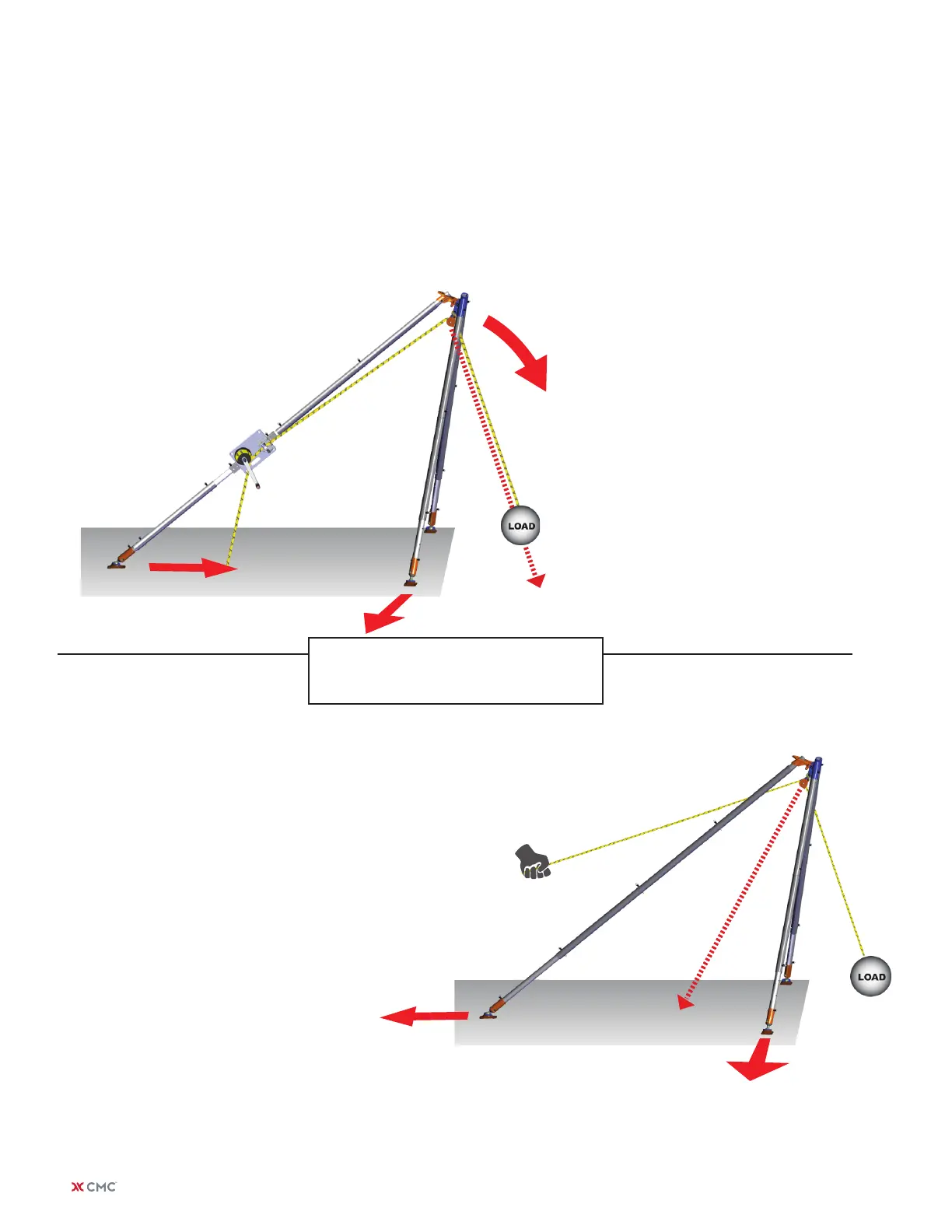
Fig. 3d
When the load is applied, the force acting
on the Anchor Frame will have a tenden-
cy to rotate the Vortex forward toward the
load as shown by the arrows.
The front legs of the Easel-Leg Tripod
will have a tendency to spread apart and
backward, while the rear leg will have a
tendency to move forward.
The rear leg of an Easel-Leg Tripod must be
appropriately secured to control all tensile,
compressive and shear (sliding) forces.
NOTE: GUY LINES HAVE BEEN OMIT
TED FROM THIS DIAGRAM FOR CLAR
ITY. Proper securing of this conguration
is absolutely critical to its safe operation.
| ARIZONA VORTEX KIT USER MANUAL18