LOAD
APPLIED
FORCE
APPLIED
FORCE
LOAD
APPLIED
FORCE
LOAD
HOBBLE STRAP
APPLIED
FORCE
HOBBLE STRAP
HOBBLE STRAP
To identify the Tendency of Movement of the feet and the
head of the frame, consider:
• The unloaded state (standing the frame prior to the
application of the load)
• The planned movements of the load
• Foreseeable misuse and potential unplanned events
The following diagrams are a guide to identifying the Ten-
dency of Movement of the head and the feet of the frame.
Fig. 3a
Fig. 3b
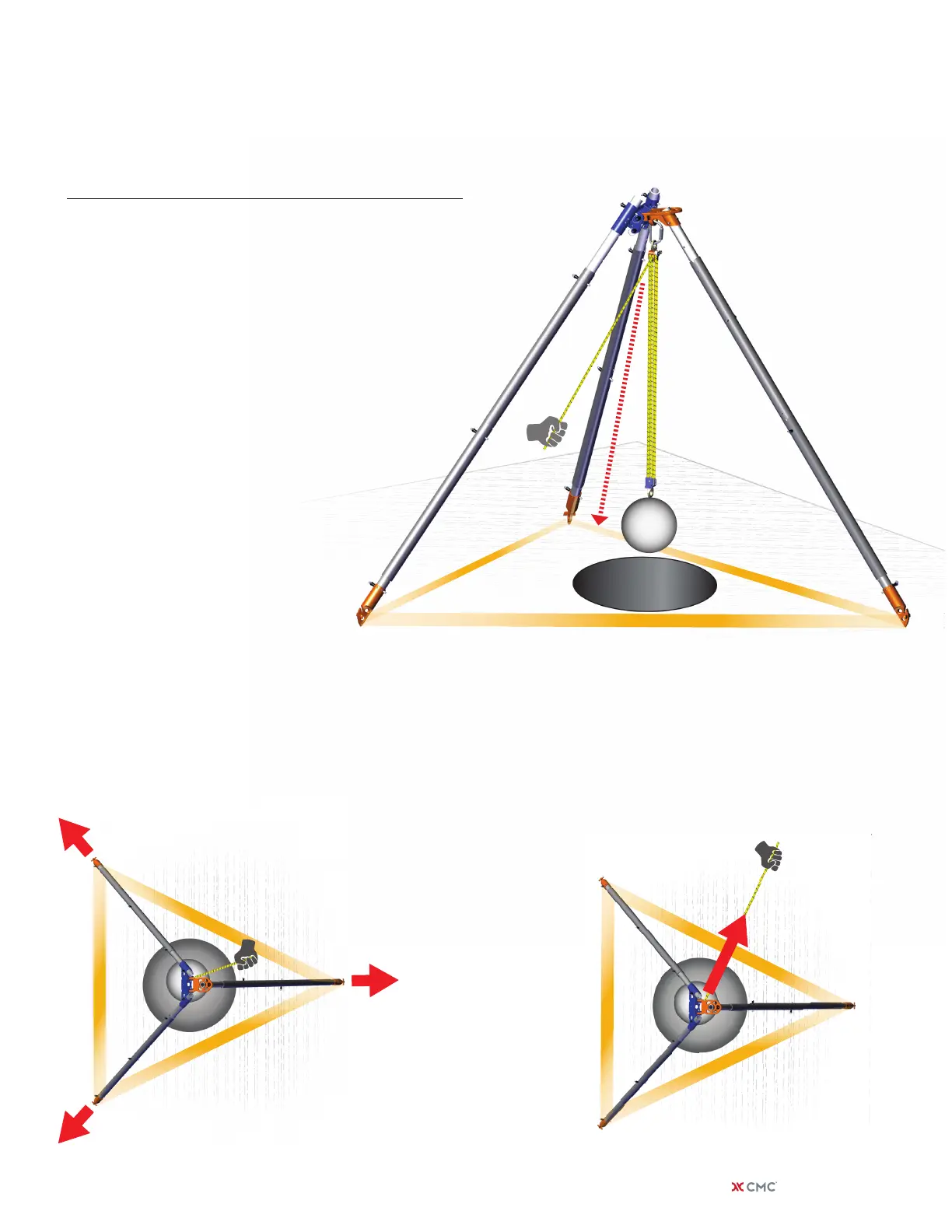
The Equal Leg Tripod shown support-
ing a CSR2 Pulley System. The applied
force in this example is the resultant
of the pulley system which is be-
tween the load and the hauling line
(closer toward the load).
This mode of use is as a Direction-
al Frame.
When force is applied on the Equal Leg Tripod,
the feet will have a tendency of movement
outward, as indicated by the red arrows.
This movement is typically prevented by the
use of hobbles between the feet. CMC
recommends that each pair of feet be
individually hobbled to obtain
maximum security and
stability.
TOP VIEW
Step 3: Tendency of Movement
Directional Frame
MODE OF USE:
CONFIGURATION:
Tripod
Fig. 3c
Care must be taken to ensure the haul line
is kept close to the load line. The frame
will have a tendency of movement in the
direction of the haul if the haul line is
extended out to the point where the
applied force (pulley system resul-
tant) approaches the hobble.
TOP VIEW
| cmcpro.com 17