EVAC-500 Voice Alarm & Evacuation System Operation Manual
4 / 42
1. Host & Extension Host EVAC-500/EVAC-240 & EVAC-500/EVAC-240RT
EVAC-500 & EVAC-240 is the core of voice alarm system, built with 500W/240W digital amplifier, enable to manual or
auto broadcast the emergency message, also fireman’s microphone evacuation is also possible under emergency,
system capacity up to 120 zones with paging and background music functions, monitoring includes amplifier failure,
speaker line failure, emergency message and emergency microphone supervision.
Emergency message format of *.wav.
EVAC message number shall be less than 255 in the file root of “evac_message/” & “alert_message/” & “prompt/”.
Make sure the software standby amplifier configuration is same as real amplifier wiring, otherwise, the host
EVAC-500 will not auto standby to backup amplifier without software correct configuration.
6 zone speaker outputs, each zone max power output is 500W, total 6 zone power output max is 500W.
With 6 external microphone or line inputs for analog microphone use or external audio sources input.
With control input and control output to inter-work with third party system.
With 3000 events history record includes power module, fireman mic, EVAC message, amplifier & speaker line.
System capacity of 32 units remote paging microphone up to 600 meters through CAT6 straight cable.
System support redundancy wiring among remote paging microphone, host and extension host within 600 meters.
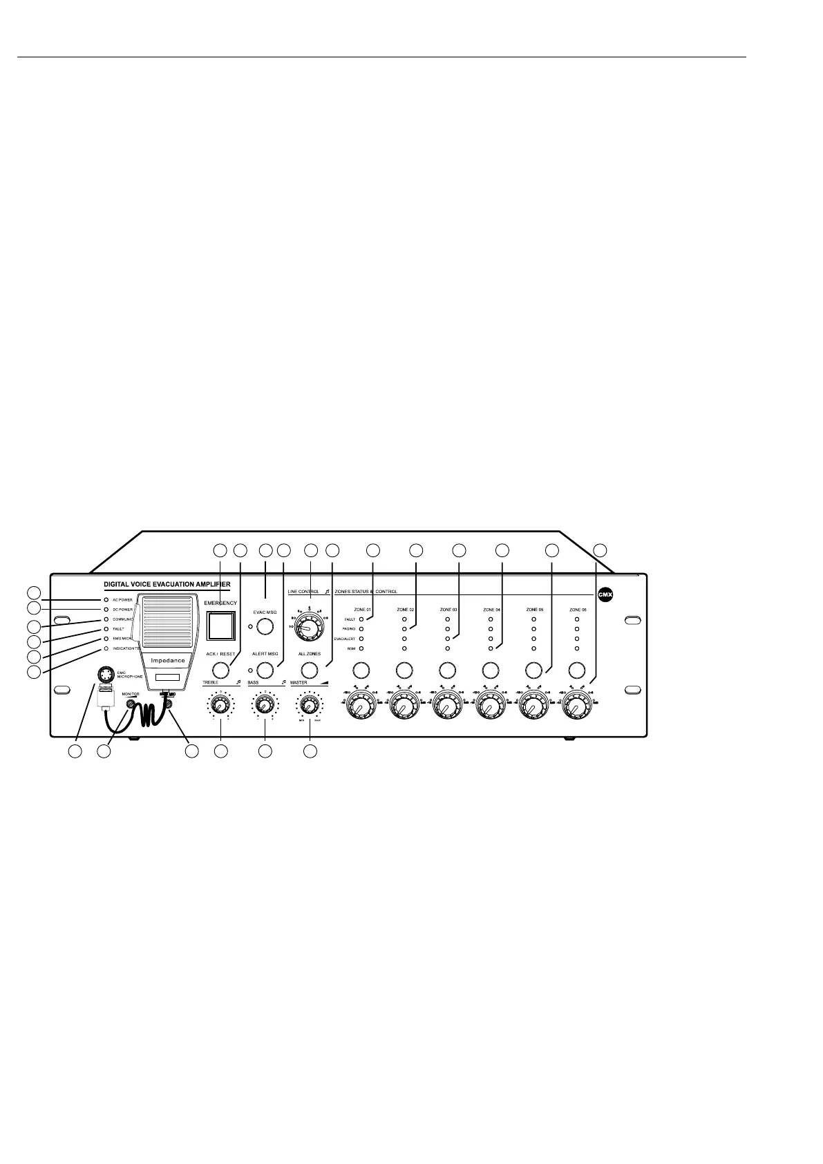
1.1. EVAC-500 & EVAC-500RT Front Panel
19
20
21
7 9
22
8 10 11
23 24
12 1413 15 16 17 18
3
4
5
6
1
2
1-AC Power Indicator.
Green----means currently host AC supply normal;
Yellow----means currently host AC supply failed.
2-24V DC Indicator.
green – means current host 24V DC standby power supply is normal;
extinguish----means Current host has no 24V DC backup power supply;
Yellow----means current host 24V DC backup power failure.
3-Communication Indicator between Host and Extension Host.
Yellow----means no logical or physical connection between host and extension host;
extinguish----means no logical or physical connection between EVAC-500SFT with host;
Green----means currently device connection is normal.