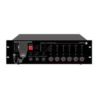
EVAC-500 Voice Alarm & Evacuation System Operation Manual
22 / 42
When the 7th dipswitch is PULL-down, all LED lights on the panel will automatically restore to their normal display
states after lighting in an order of Red → Green → Yellow. It is used mainly to test whether the display of LED lights is
normal or not.
“8”— Device terminating resistance control, used to ensure the microphone line always monitored.
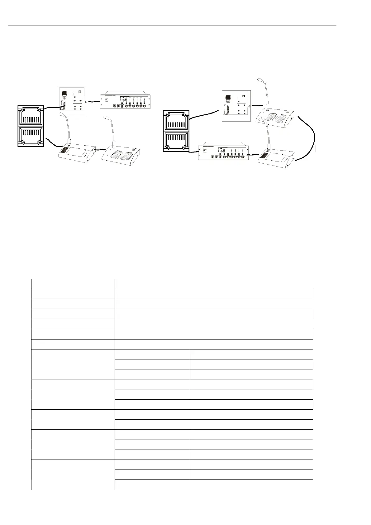
Please refer to the following connection:
Pic 1 Pic two
Note:
1. If the EVAC-500FM, EVAC-500RM, EVAC-500TM or EVAC-500RT can not communicate with the host (EVAC-500)
normally, enable the EVAC-500RM terminating resistor, That is, unplug the "8" bit, prohibit the working of EVAC-500FM
or through the touch interface to open the EVAC-500TP terminal matching resistor, by this way the system connection
can be non-loop;
2. Similar to the "Pic Two" of the loop connection, it is need to prohibit all external devices terminal resistance, so the
system loop connection is recommended for more stable performance.
4.2. Technical Specification
Model EVAC-500RM
Description Remote Paging Microphone
System Capacity 32 units
Communication Distance 600 meters
System Connection Star connection or loop redundancy connection
Zone Number 12 zones or 12 groups
Paging Mode PPT & normal paging modes
Electrical Part Phantom Power Voltage
20V-27.5V
Max Current <0.1A
Power Consumption <2.4W
Line Input Sensitivity 775mV
Impedance 10kΩ
S/N Ratio >70dB
Microphone Input Sensitivity 5mV
Impedance 600Ω
Working Environment Operation Temp +5 ~ +40℃ ℃
Storage Temp -20 ~ +70℃ ℃
Relative Humidity < 95%
Mechanical Part Dimension 153*52*175
Weight 0.8kg
Finish Aluminum case in black