GR712RC-QSG
November 2018, Version 1.0
4 www.cobham.com/gaisler
2. Board Configuration
2.1. Overview
The primary source of information for board configuration is the GR712RC Development Board User Manual.
The board requires some hardware configuration to fit with the customer requirements. In particular, the number of
the GR712RC-BOARD's processor I/O pins limits the simultaneously available connections to external interfaces.
To overcome this limitation, the SoC features an internal switch matrix, and a set of jumpers must be configured
accordingly to route the signals to the appropriate headers on the board. The internal switch matrix is configured
by enabling the respective interfaces via software. Additionally, clock selection might need to be configured by
a set of jumpers and possibly the insertion of custom oscillators.
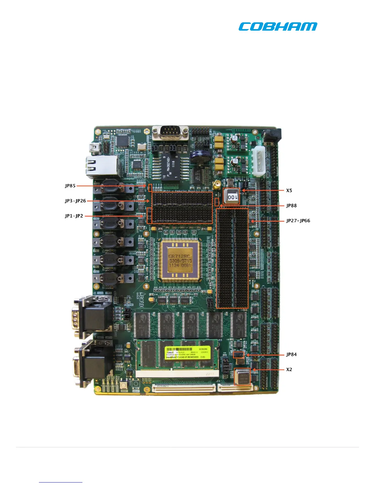
Figure 2.1. GR712RC-BOARD default configuration as delivired
2.2. Clock Sources
The minimum requirement in order for the board to work and to be able to connect to it, is that the clock sources
are properly configured. The 80 MHz oscillator in socket X2 provided by default with the board is connected to
 Loading...