191
SAILOR FleetBroadBand
Training Manual
6
6.3.2 R&R of Antenna Tracking Receiver Module
(ATR)
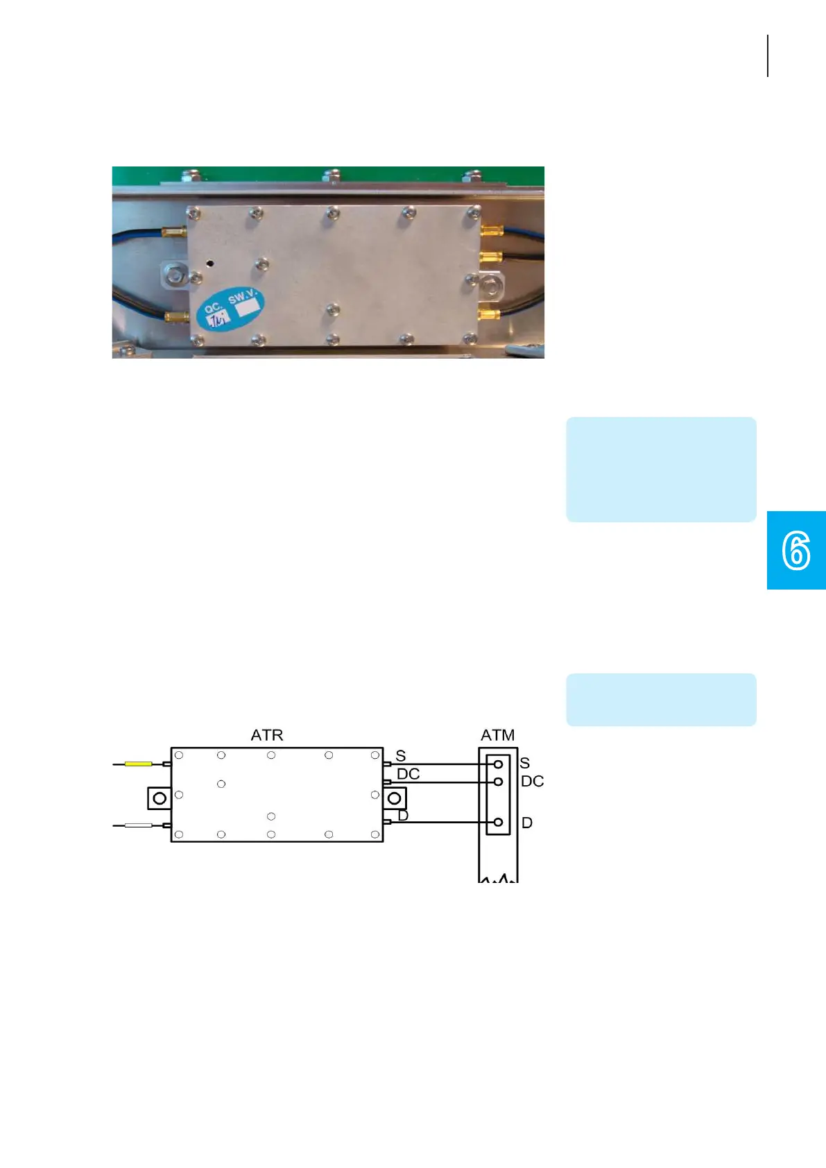
Figure 6-17: TT-3052B/C ADU, Antenna Tracking Receiver Module
Removal:
1. Remove the Radome Top as described in the previous section
Remove & replacement of Radome Top.
2. Disconnecttheve(5)plugsoftheATRModule,two(2)on the
left hand side and three (3) on the right hand side.
3. Unscrew the two (2) 5 mm hex screws on either side of the
ATR Module, put aside the screws as they are going to be
reused in the replacement of the ATR Module.
4. Carefully remove the ATR Module.
Replace:
1. Carefully position the new ATR Module (S-62-128257) over
the studs on the antenna frame.
2. Fasten the two (2) 5 mm HEX screws (removed in above
Removal: step 3) with no more than 1.2 Nm.
3. Reconnect the plugs (follow the diagram below), make sure
thattheyareproperlytted.
Figure 6-18: TT-3052B/C ADU, ATR to ATM connection
4. Reinstall the Radome Top as described in previous section
Remove & replacement of Radome Top.
NOTE!
Take a note of the exact
position of each plug.
NOTE!
Do not pull the wires - pull the
plugs.
NOTE!
A click should be heard when
the plug is fully inserted.
 Loading...