Do you have a question about the COBHAM SAILOR 100 GX and is the answer not in the manual?
Manual intended for installers and service personnel, emphasizing safety requirements.
Provides a summary of the manual's chapters and appendices.
Specifies the software version covered by this manual for ADU and ACU.
Explains the use of bold and italic text for emphasis and cross-references.
Defines warning, caution, note, and important text types and general safety advice.
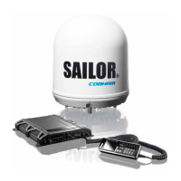
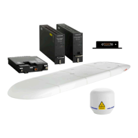
Overview of the SAILOR 100 GX system, its components, and capabilities.
Details available options and their part numbers for the SAILOR 100 GX system.
Instructions for unpacking the ADU, ACU, and GMU and checking contents.
Guidelines for installing the ADU for optimal system performance.
Step-by-step procedure for installing the ADU on the mast.
Procedure for installing the ACU in a 19” rack.
Procedure for installing the GMU in a 19” rack.
Diagram and instructions for connecting the ADU, ACU, and GMU.
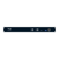
Overview of ACU's LEDs, display, keypad, and connector panel.
Overview of the GMU's connector panel and interfaces.
Options for powering the ACU and GMU, including DC and AC sources.
Information on selecting power cables and measuring source impedance for the ACU.
Step-by-step guide for powering up the ACU and GMU.
Using the ACU's web interface for system configuration.
Procedures for calibrating the system, including satellite, heading, azimuth, and cable.
Navigating the web interface for settings like blocking zones, LAN, and e-mail.
Description of the ACU display elements, keypad navigation, and menu structure.
Information on SNMP support for system monitoring and configuration.
A checklist for verifying the correct installation of the antenna system.
Checklist for verifying ACU, GMU, connectors, and wiring installation.
Functional tests to perform in harbor to ensure system operation.
Information on accessing help desk and downloading diagnostic/statistics reports.
Step-by-step instructions for updating ADU, ACU, and GMU software.
Managing satellite and VSAT modem profiles for optimal connection.
Understanding system status through LEDs and status messages.
Note that ACU has no user-replaceable parts; contact service.
Instructions for replacing various modules within the ADU.
Updating calibration data after replacing VIM2 or PCM modules.
Guidelines for inspecting ADU mechanical components for critical wear.
Initial checks and guidelines for troubleshooting the SAILOR 100 GX system.
Procedure for returning units for repair or contacting service partners.
Detailed specifications for the SAILOR 100 GX system components.
Outline drawings of the ADU, ACU, and GMU for dimension reference.
Reasons for grounding the system: safety and ESD protection.
Recommendations for grounding the ACU and extending the ground plane.
Grounding methods for steel hulls, including ACU and ADU grounding.
Grounding methods for aluminum hulls, including ACU and ADU grounding.
Grounding methods for fiberglass hulls, including ACU and ADU grounding.
Instructions for constructing and connecting a separate ground cable.
Measures to mitigate RF interference from nearby transmitters.
Specifications for the jumper cable used for grounding.
Overview of event detection during POST, PAST, and CM, and event message display.
A table listing ADU error codes, units, severity, descriptions, and explanations.
A table listing ACU error codes, PCBs, severity, descriptions, and explanations.
Using Telnet for system configuration and VSAT modem parameter setup.
Detailed descriptions of supported CLI commands.
Confirmation of CE certification according to the R&TTE Directive.
| Operating Temperature | -25°C to +55°C |
|---|---|
| Polarization | Circular |
| Stabilization | 3-axis |
| Type | Maritime VSAT |
| Frequency Band | Ka-band |
| Data Rate | Up to 50 Mbps |
| Modem Unit | iDirect |
| Survival Temperature | -40°C to +70°C |
| Power Supply | 100-240 VAC, 50/60 Hz |
| Frequency Range | 19.2 - 20.2 GHz (Rx) |