Interfaces of the ACU
99-145912-A Chapter 4: Interfaces 4-5
4.1.7 LAN1 – 4 connectors
The ACU has four Ethernet connectors (type RJ45) for connecting to the
GMU, PC/lap tops, routers, wireless access points. The maximum cable
length per connection is 100 m. The Ethernet cable type must be CAT5,
shielded.
1. Connect an Ethernet cable to Port 1 at the ACU and to the upper
leftmost LAN connector at the GMU.
2. Use Port 2 for user WAN (Internet etc.).
3. Connect an Ethernet cable to Port 3 and to the LAN connector on
the left side of the rear panel if you want to use the front LAN
connector of the ACU for system control.
4. Use Port 4 (network 3) to connect the SAILOR 100 GX to the vessel’s
LAN
For more details about the LAN networks see To configure the LAN
network on page 6-24.
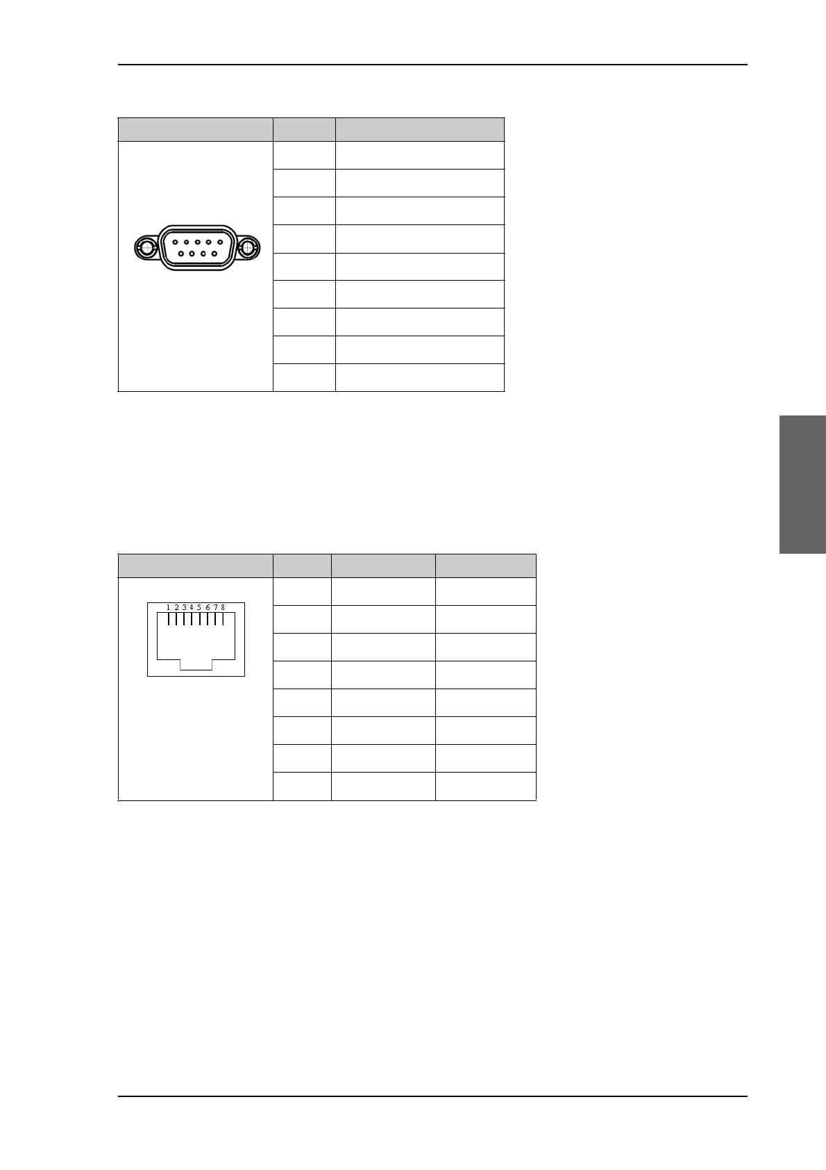
Outline (on the ACU) Pin Pin function
1Ground
2Line A RXD (+)
3Line B TXD (-)
4Ground
5Ground
6 Not connected
7Line A RXD (-)
8Line B TXD (+)
9 Not connected
Table 4-6: RS-422 connector, male, outline and pin assignment, ACU
Outline Pin Pin function Wire color
1Tx+ White/orange
2Tx- Orange
3 Rx+ White/green
4 Not connected Blue
5 Not connected White/blue
6Rx- Green
7 Not connected White/brown
8 Not connected Brown
Table 4-7: Ethernet connector, outline and pin assignment

 Loading...


