Interfaces of the GMU
4-6 Chapter 4: Interfaces 99-145912-A
4.2 Interfaces of the GMU
The following sections describe the connectors of the GMU and how to
connect to the ACU, power and other equipment.
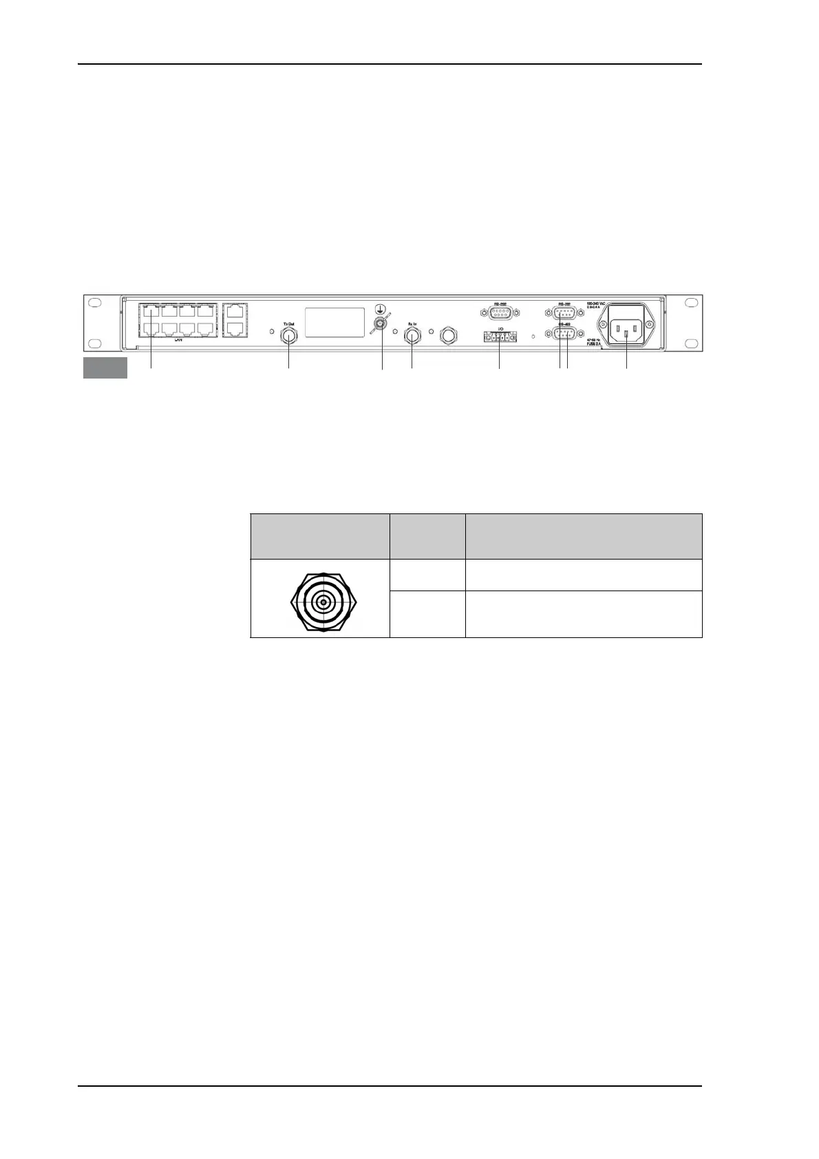
4.2.1 Connector panel
The following figure shows the connector panel of the GMU.
4.2.2 Rx In and Tx Out connectors
The GMU has an Rx In and a Tx Out connector. Use these connectors to
connect the ACU to the GMU.
Figure 4-4: Connector panel of the GMU
&RQWUROYLD$&8 7[2XW 5[,Q*URXQG
7[0XWH
5[/RFN
5656 $&3RZHU
*08
Outline
(on the ACU)
Pin
number
Pin function
1 Inner conductor: 50 MHz clock, Rx/Tx
2 Outer conductor: GND (Shield)
Table 4-8: F connector, Rx and Tx, outline and pin assignment

 Loading...


