Interfaces of the GMU
99-145912-A Chapter 4: Interfaces 4-7
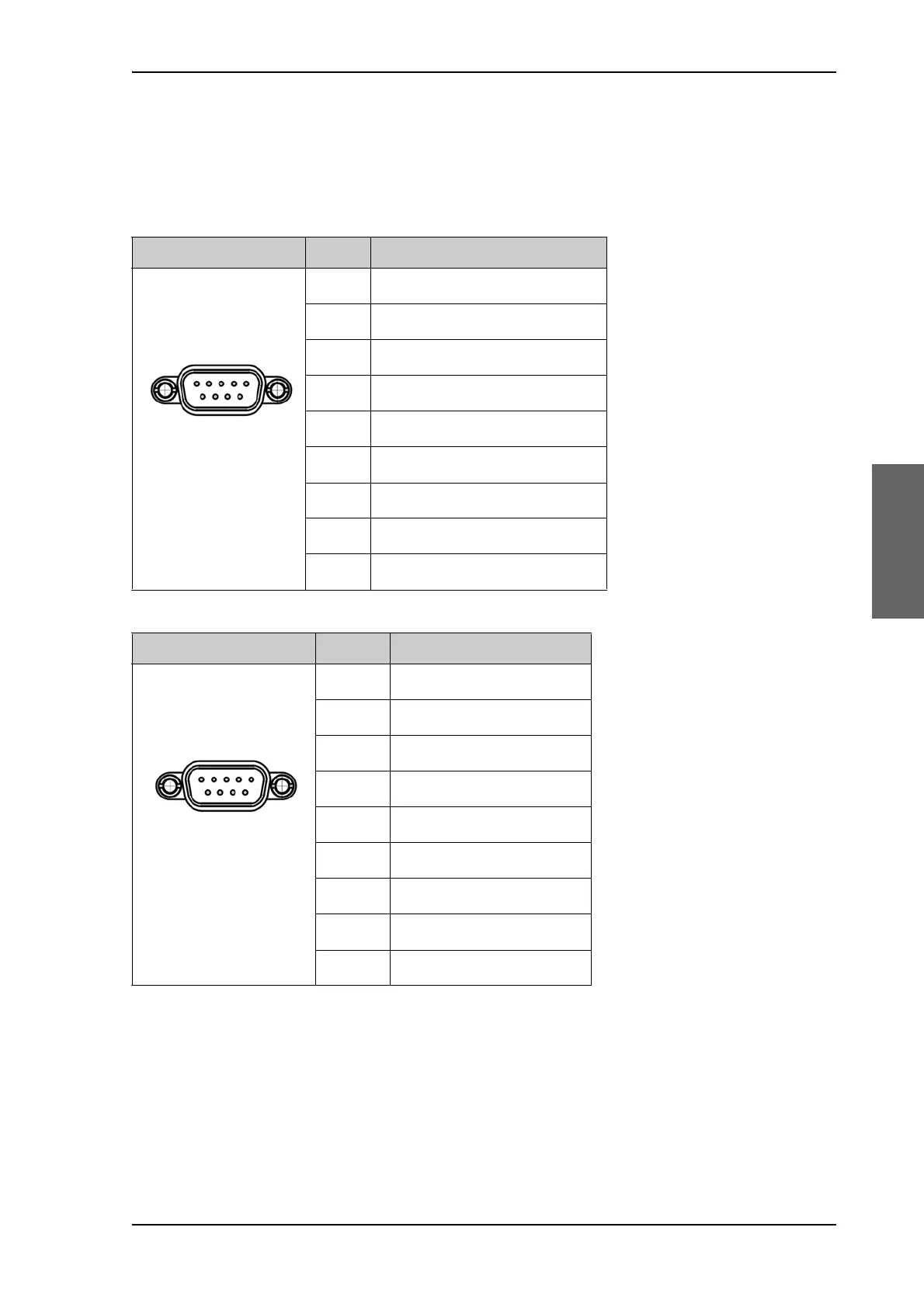
4.2.3 RS-232 and RS-422 connectors
The GMU has two RS-232 and one RS-422 connector for control
information to and from the ACU. See section To connect the ADU, ACU
and GMU on page 3-26 for details how to connect the ACU to the GMU.
Outline (on the GMU) Pin Pin function
1 Not connected
2BUC TXD
3BUC RXD
4 Not connected
5GND
6Power good
7GMU reset
8 Temperature out of range
9Core module RSS
Table 4-9: RS-232 connector, male, outline and pin assignment, GMU
Outline (on the GMU) Pin Pin function
1GND
2Keyline P
3 Reset P
4GND
5GND
6 Not connected
7Keyline N
8 Reset N
9 Not connected
Table 4-10: RS-422 connector, male, outline and pin assignment, GMU

 Loading...


