Interfaces of the ACU
4-2 Chapter 4: Interfaces 99-145912-A
4.1.2 DC Input connector
The ACU must be provided with DC power, for example by using the
SAILOR 6080 AC/DC Power Supply or 24 VDC from the vessel’s power
supply.
DC input: Female plug (Weidmuller, Part number 1930050000) for
wires up to AWG10/6 mm
2
(included in the delivery).
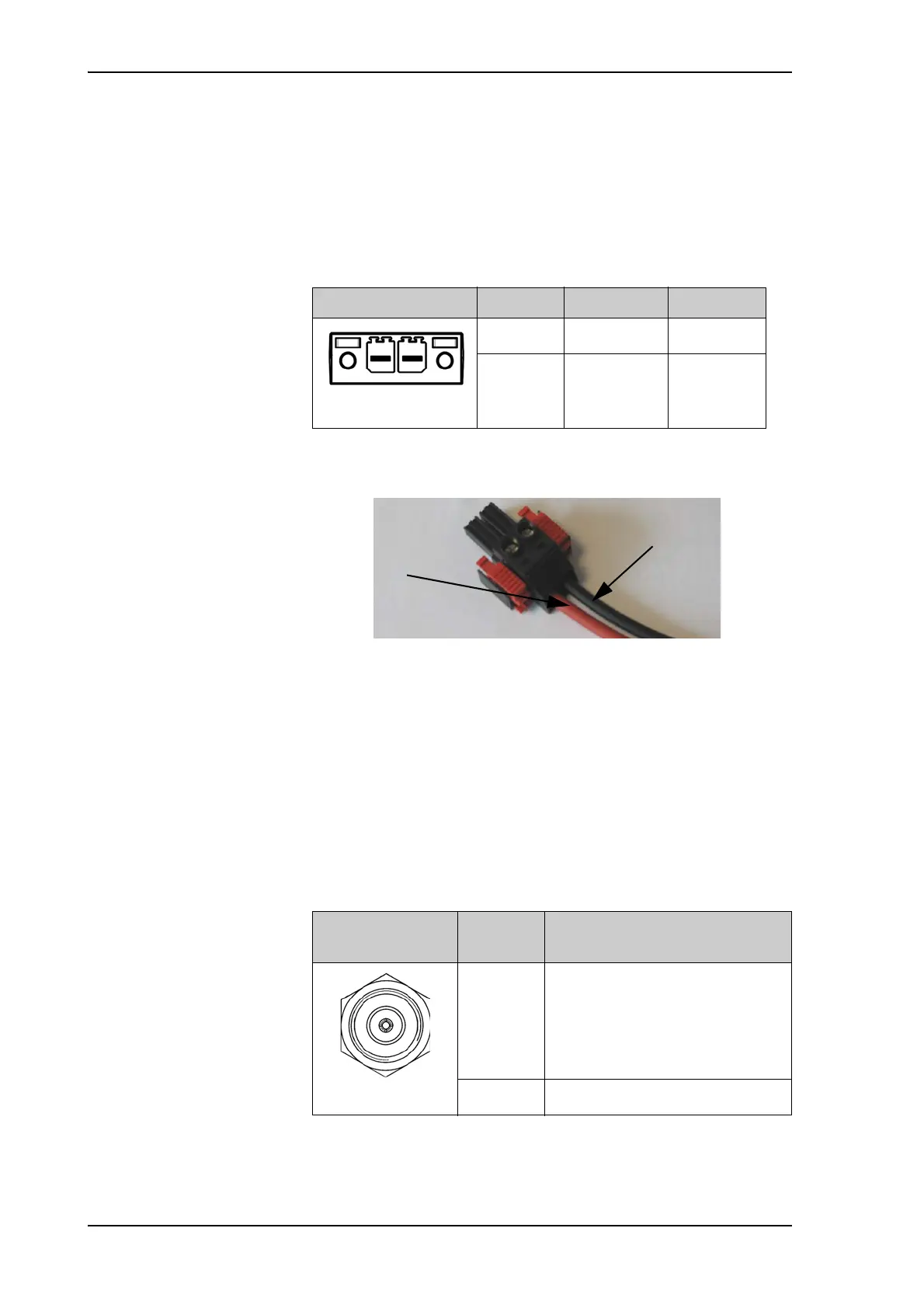
1. Insert the power cable as shown below.
2. Plug in the connector.
3. Fasten the connector with the two red clamps.
For more information about power supply and power requirements see
the chapter Power and startup on page 5-1.
4.1.3 ADU connector
There is just one cable from the ACU to the ADU. This is used to power
the ADU, supply a reference clock, handle all communication between
ACU and ADU, and deliver the GX Rx and Tx signals.
Outline (on the ACU) Pin Pin function Wire color
Left Vin+ Red
Right Vin- Black
Table 4-1: DC Input plug, outline and pin assignment
Figure 4-3: DC Input connector with power cable
Outline
(on the ACU)
Conductor Pin function
Inner DC to ADU
reference clock to ADU
ACU to ADU internal
communication
GX Rx/Tx
Outer GND (Shield)
Table 4-2: N connector, outline and pin assignment

 Loading...


