Removal and replacement of ADU modules
8-60 Chapter 8: Service & maintenance 99-145912-A
8.6.10 To replace the Inertial Sensor Module
(ISM)
Locate the ISM, see Overview on page 8-11.
To remove the ISM, do as follows:
8.6.11 To replace the RF Pack
To remove the RF Pack do as follows:
1. Open the service hatch by releasing the two latches.
2. Switch off the power to the antenna on the service switch.
3. Turn and tip the antenna so the feed horn faces you.
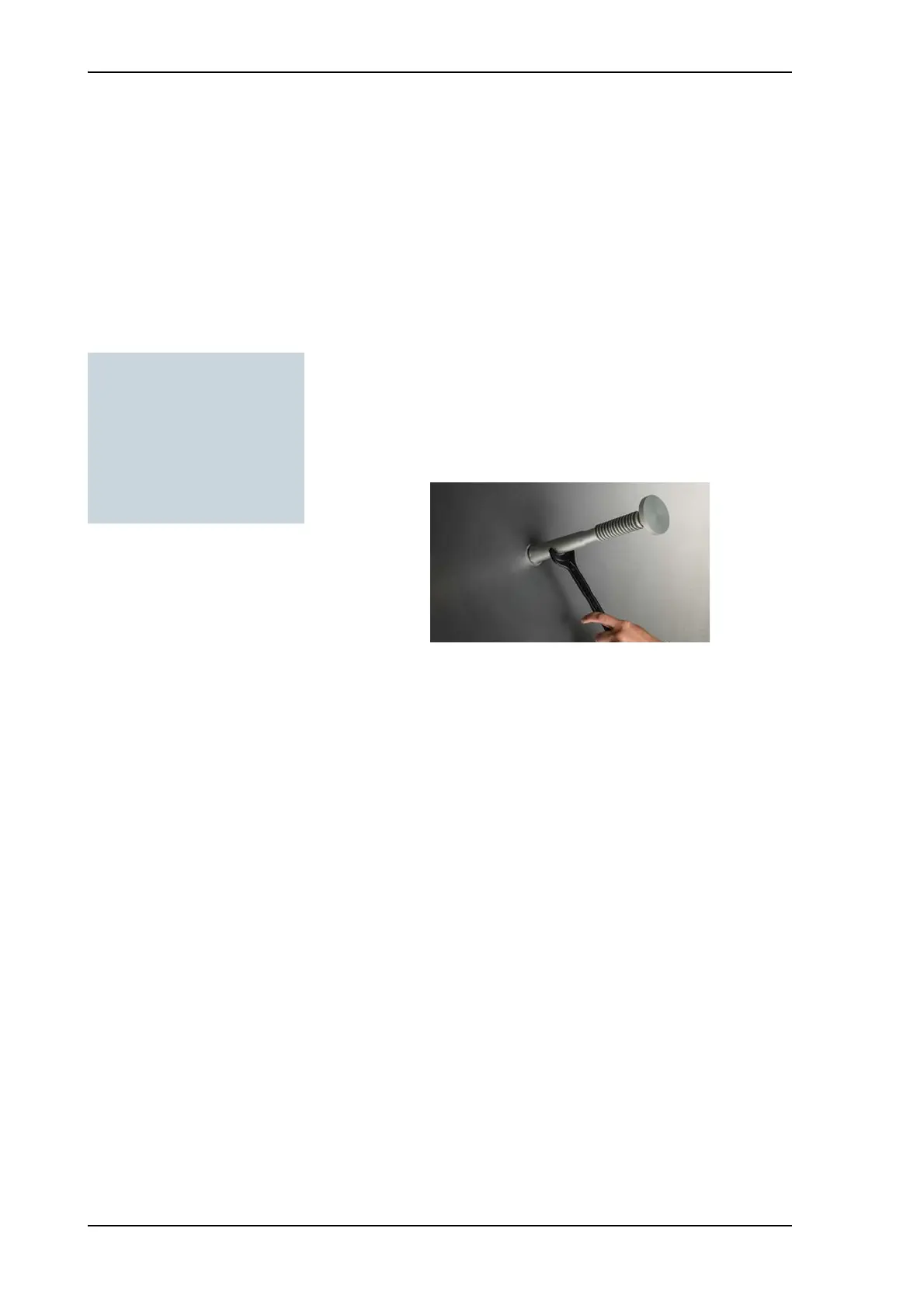
4. With the wrench remove carefully the Ka feed horn.
5. Rotate the antenna dish to top position.
6. Press in and turn the elevation locking pin to locked position.
7. Disconnect the four cables of the cable wrap; one SMA to LNB, one
SMA to blind terminator, one SUB-D to BCM (marked S-BUS IN) and
one N-connector to BCM (marked VIM).
Figure 1-17 & 1-18 can be used (Conversion kit manual)
Tools needed:
•Wrench
• 4 x 150 mm Allen key
(located inside the service
door of the ADU)
•Flat head screw driver
Figure 8-76: Removal of the Ka feed horn

 Loading...


