99-145912-A 4-1
Chapter 4
Interfaces 4
This chapter has in the following sections:
• Interfaces of the ACU
• Interfaces of the GMU
4.1 Interfaces of the ACU
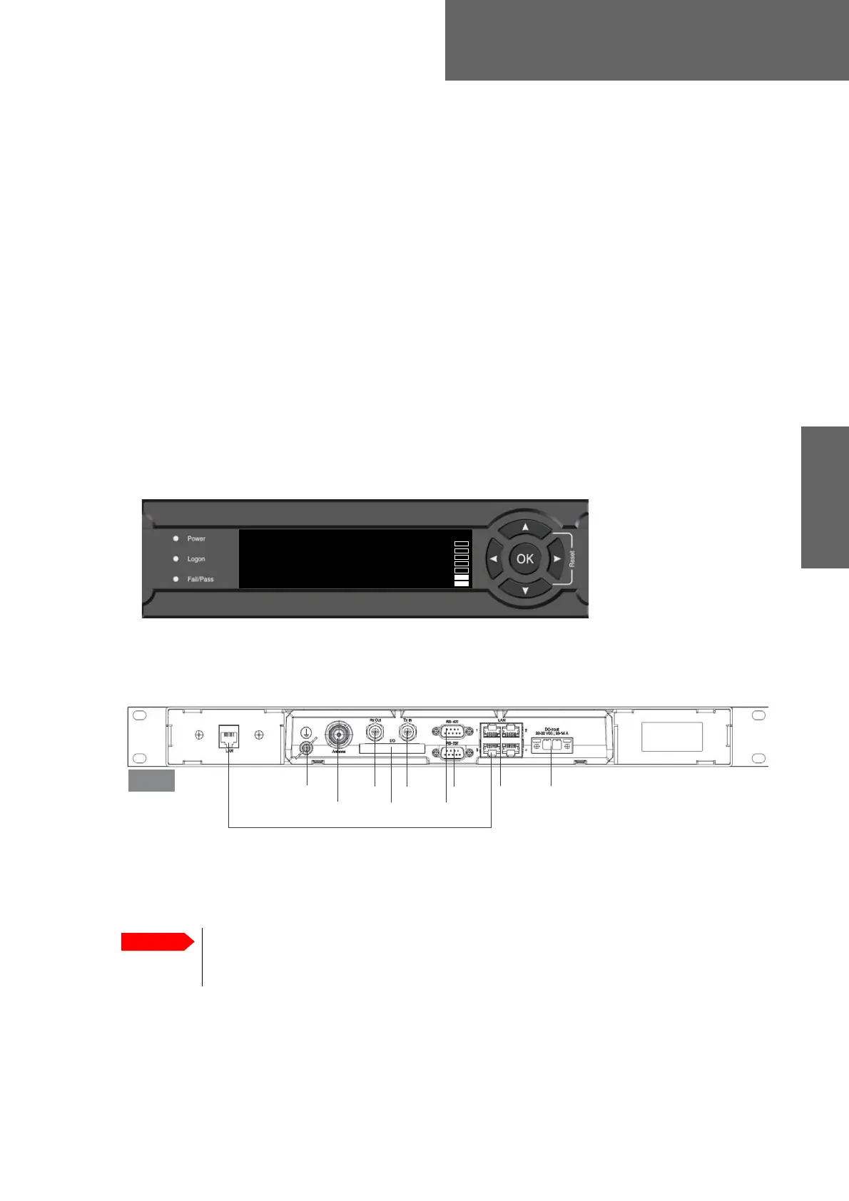
4.1.1 LEDs, display, keypad and connectors
The following figure shows the LEDs, display and the keypad of the ACU. For
an explanation of the texts in the display see ACU display and keypad on
page 6-39.
The following figure shows the connector panel of the ACU.
The connector LAN on the front panel is typically connected to the service
port at LAN3 with a straight Ethernet cable. Then you can access the service
port from the front of the ACU rack version.
Figure 4-1: ACU: LEDs, display and keypad (detailed, example)
0DLQ1$9*+0'01(72./$1±
75$&.,1*
6$7:5;/+7;0$5
Figure 4-2: ACU (connector panel)
/$1WRIURQW
7[,Q5[2XW*URXQG
/$1
56
10($
'&3RZHU
56
$QWHQQD
$&8
Connect the Ethernet cable between LAN 3and LAN to provide
connection to the service port (LAN connector) at the front of
the ACU.

 Loading...


