Removal and replacement of ADU modules
8-34 Chapter 8: Service & maintenance 99-145912-A
8.6.6 To replace the Pedestal Control Module
(PCM)
The PCM controls the antenna dish and the polarization mechanism
assembly with the three DC motors and a step motor. Communication
between the PCM and ACU is done via the VIM2. The VIM2 is also
controlled by the PCM via a parallel interface cable.
The PCM is the communication master of the ADU serial-bus
connecting the DDM, PMM and ISM. Communication to the GPS
Module and power to all modules is via S-bus.
The PCM has two LEDs for status and troubleshooting:
•Power LED: green or Off
•Service LED: green or red
To replace the PCM, do as follows:
1. Open the service hatch.
2. Switch off the power to the antenna on the service switch.
3. Rotate the antenna pedestal so that the Pedestal Control Module
(PCM) faces the service hatch.
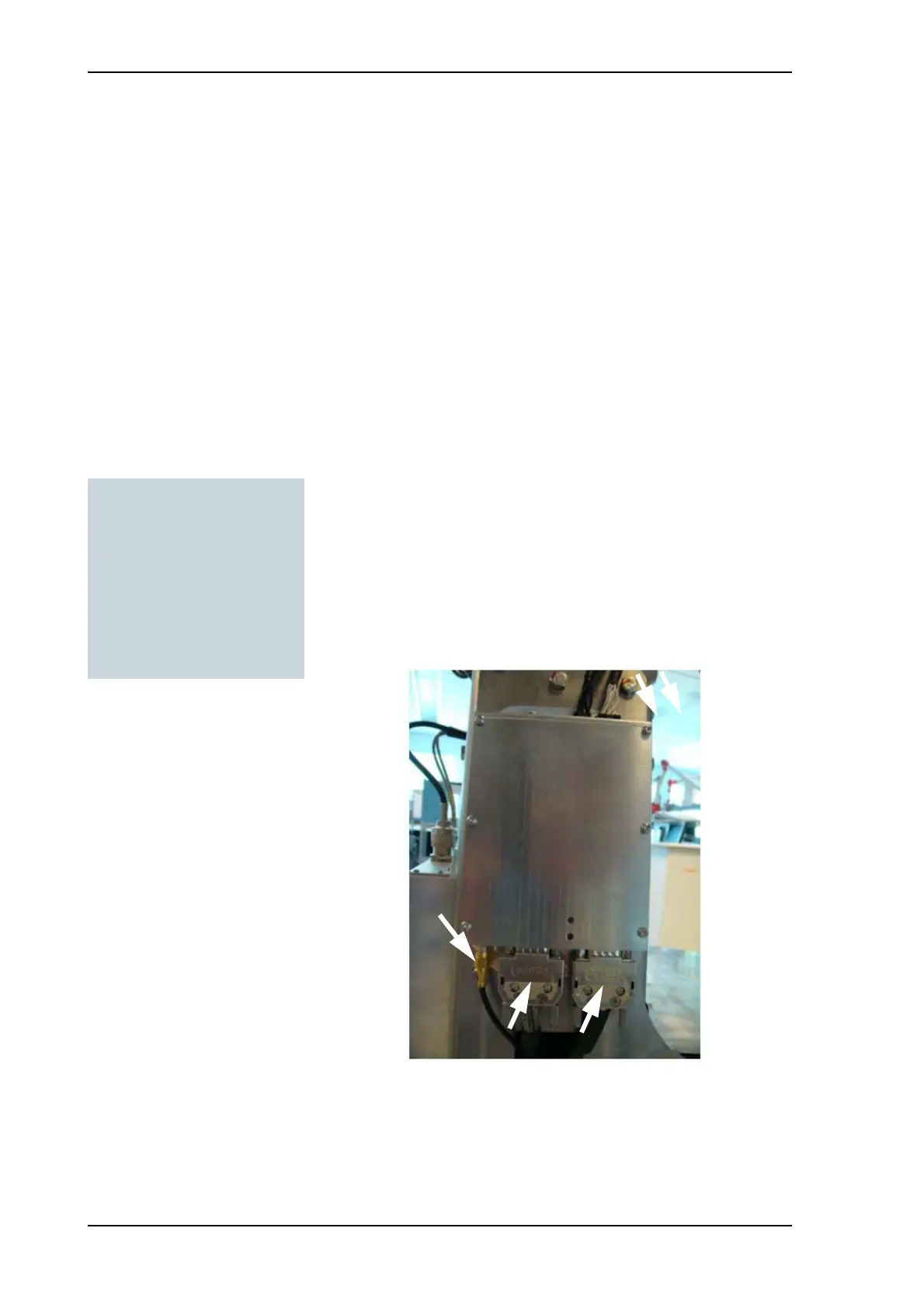
4. Disconnect the 2 connectors at the top, then the 2 SUB-D
connectors at the bottom, then the SMA connector at the bottom
(left) of the PCM.
5. Remove the 4x4 mm Allen screws (thread size M5) (all become
visible when the connectors are removed) and remove the PCM.
Tools needed:
•TX20
• 4 x 150 mm Allen key
(located inside the service
door of the ADU)
•Flat head screw driver
• 8 mm open-end spanner
Figure 8-34: Removing the PCM — connectors

 Loading...


