Removal and replacement of ADU modules
99-145912-A Chapter 8: Service & maintenance 8-33
5. Disconnect the 4 connectors from the BCM (mark them to avoid
mistakes).
6. Remove the 4x4 mm Allen screws (thread size M5).
If access for some reason is limited, remove the Ka RF-pack, see section
TBD.
To insert a new BCM follow the instructions above in reverse order -
while observing the following guidelines:
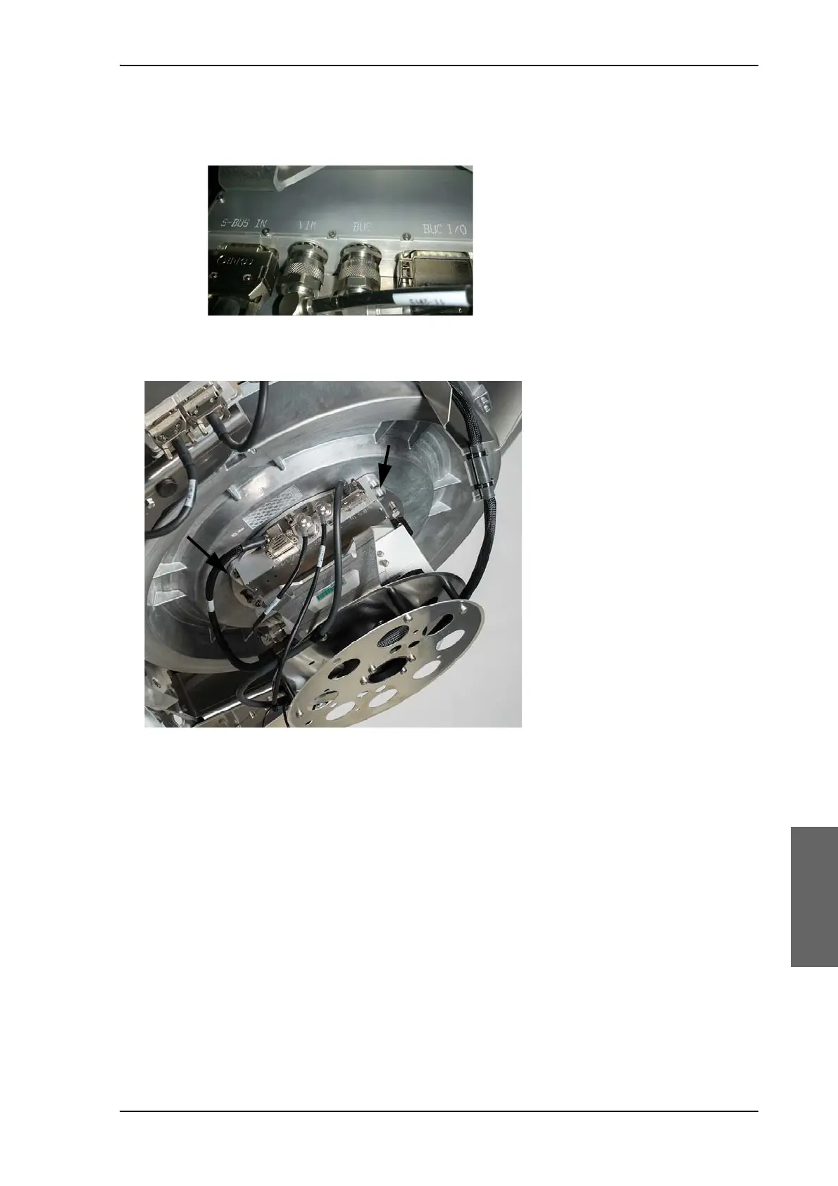
1. Observe the marking on the BCM:
• S-BUS IN: SUB-D connector linking BCM to other modules via the
S-bus
• VIM: N-connector, cable connected to VIM2
• BUC: N-connector connecting BCM to BUC
• BUC I/O: SUB-D connector, connecting BCM with BUC
See figure Figure 8-32: Connectors at the BCM.
Figure 8-32: Connectors at the BCM
Figure 8-33: Cable connection from the cable wrap

 Loading...


