SAILOR 100 GX system
2-6 Chapter 2: Introduction 99-145912-A
Four lifting brackets (included in the delivery) and reuse of packing
material help getting the ADU safely into place. Satellite profile
parameters are entered in the built-in web server of the ACU, using a PC.
The system configuration is saved in two modules, there is no loss of
data at repair. The large service hatch of the radome gives easy access
to the ADU on site. The service switch in the ADU stops the DC Motor
Driver modules and turns the BUC off. The service tools for replacing
modules are placed on a tool holder inside the radome.
All modules have a service and power LED status indicator. Each module
is encapsulated in a metal box with self-contained mounting bolts. If
necessary, belts and modules can be exchanged through the service
hatch on site.
You can do remote diagnostics and service with the ADU. Its built-in
test equipment constantly checks the modules for proper functioning, it
monitors and logs information for all modules. The ADU performs a
POST (Power On Self Test) and you can request a self test (PAST, Person
Activated Self Test) and Continuous Monitoring (CM). Error codes can
be read out in the web interface and in the display of the ACU.
The ADU software is updated automatically when you make a software
update of the ACU.
2.1.3 Antenna Control Unit (ACU)
The ACU is the central control unit in the system. It contains all user
interfaces and manages all communication between the ADU and the
connected GMU, a connected PC and an optional FleetBroadband
service communication line. The ACU has a display, status LEDs and a
keypad. It provides a DHCP client. During configuration you can
configure heading offset, save satellite setups and enter No Transmit
Zones (blocking zones in which the ADU does not transmit).
The user PC (user WAN) for Internet access etc. is connected to the
ACU, not the GMU.
The ACU provides DC power to the ADU through a single coaxial cable.
You can use the SAILOR 6080 AC/DC Power Supply to provide the DC
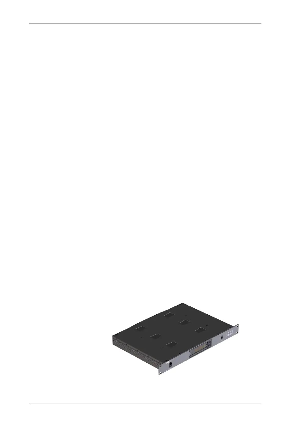
power to the ACU. The ACU comes in a 19” rack version.
Figure 2-6: Antenna Control Unit

 Loading...


