SAILOR 100 GX system
99-145912-A Chapter 2: Introduction 2-7
You can do remote diagnostics and service with the ACU. Its built-in test
equipment constantly checks the device for proper functioning. It
performs POST (Power On Self Test) and you can request a PAST (Person
Activated Self Test). Continuous Monitoring (CM) is also available. BITE
error codes can be read out in the web interface and in the display of the
ACU.
You can make a software update with a connected PC and the built-in
web interface of the ACU.
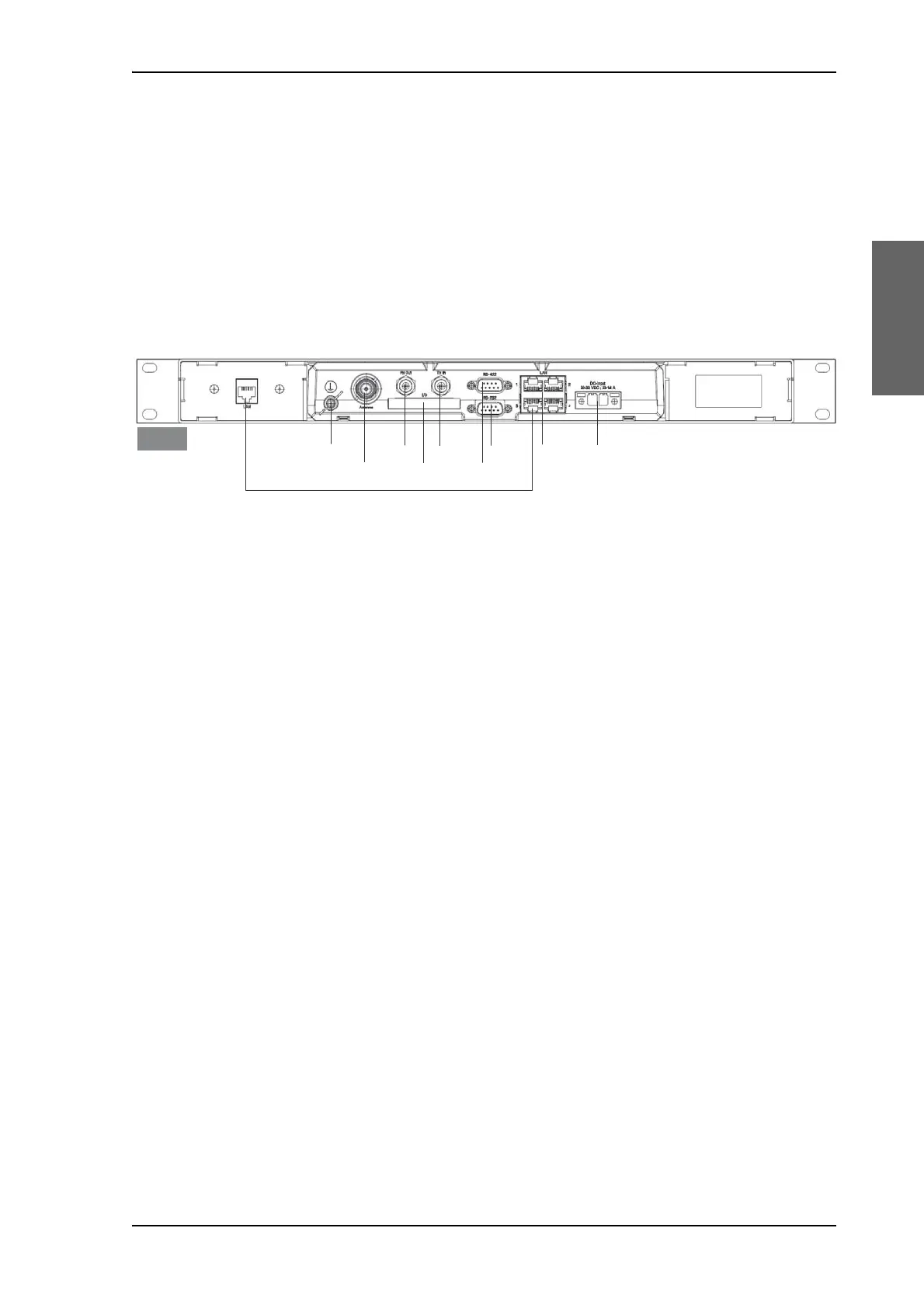
The ACU has the following interfaces and switch:
• N-connector for ADU cable (50 Ohm).
• 2 x F connectors for Rx and Tx cables (75 Ohm) to GMU.
• Multi connector for NMEA interfaces (for input from GPS compass or
Gyro compass).
• RS-422 interface for modem control.
• RS-232 interface for modem control.
• 4 x LAN ports for modem control and user equipment.
• Ground wing nut
• Power connector.
• On/Off power switch (at the front).
The ACU also has a LAN connector at the front to access the service port
from the ACU front panel.
Figure 2-7: ACU (connector panel)
/$1WRIURQW
7[,Q5[2XW*URXQG
/$1
56
10($
'&3RZHU
56
$QWHQQD
$&8

 Loading...


