Installation of the ADU
99-145912-A Chapter 3: Installation 3-23
3.3.4 Alternative ADU cable
The allowed RF loss in the antenna cable must be maximum 20 dB RF
loss @ 1950 MHz and maximum 35 dB RF loss @ 4450 MHz. You can
verify the cable attenuation margin with the cable calibration, see Cable
calibration on page 6-11 for more details.
The DC-resistance loop of the antenna cable must be maximum 0.9
Ohm. This is to ensure the power requirements from ACU to the antenna
and to ensure the performance of the system. Preferably choose one of
the cable types listed in the table below.
If you want to use an alternative ADU cable make sure that the following
requirements are fulfilled:
1. Check the data sheet from the cable supplier to verify the values:
The RF-attenuation and the DC-resistance are below the maximum
values specified below:
• ADU cable RF-attenuation at 1950 MHz: Max. 20 dB including
connector.
• ADU cable RF-attenuation at 4450 MHz: Max. 35 dB including
connector.
• ADU cable modem-attenuation at 10 MHz: Max. 2 dB
• ADU cable modem-attenuation at 36 and 54 MHz: Max. 4 dB
• ADU cable loop DC-resistance max: 0.9 Ohm.
2. Respect the specified minimum bending radius, see the
documentation from the cable supplier. If this is not the case, the loss
in the cable will increase.
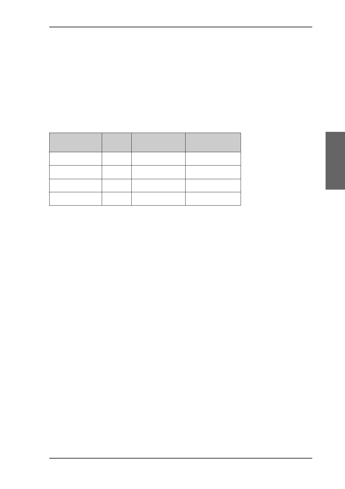
Cable Type Thickness
Absolute maximum
length (m)
Absolute maximum
length (ft)
RG214 3/8” 50 m 160 ft
LMR-400-DB 0.405” 85 m 280 ft
LMR-600-50 1/2” 150 m 490 ft
LDF4.5-50 Andrew 5/8” 270 m 810 ft
Table 3-7: ADU cable types and maximum lengths

 Loading...


