SAILOR 100 GX system
2-8 Chapter 2: Introduction 99-145912-A
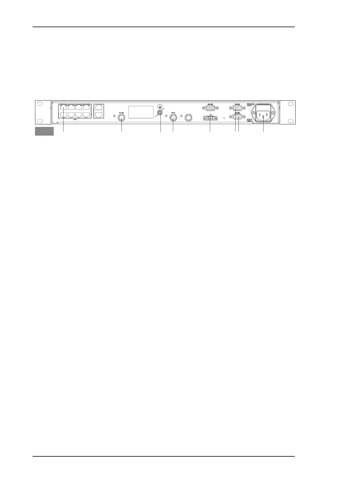
2.1.4 GX Modem Unit (GMU)
The GMU is the modem in the system. The GMU comes in a 19” rack
version.
The GMU has the following interfaces and switch:
• 8 + 2 ports, one active for modem control and user equipment.
• 3 x F connectors for Rx and Tx cables (75 Ohm) to ACU (Rx2 not
active)
• RS-422 interface for modem control.
• 2 x RS-232 interfaces, one for modem control, one not active.
• I/O connector for Tx Mute and Rx Lock.
• Ground wing nut.
• AC Power connector.
• On/Off power switch (at the front).
2.1.5 Satellite type approvals
For a list of satellite type approvals see Appendix E, Approvals.
2.1.6 Service activation
Before you can start using the SAILOR 100 GX, you need to activate the
system for the GX service. Contact your service provider for activation.
Figure 2-8: GMU (connector panel)
&RQWUROYLD$&8 7[2XW 5[,Q*URXQG
7[0XWH
5[/RFN
5656 $&3RZHU
*08

 Loading...


