99-145912-A 6-1
Chapter 6
Configuration 6
This chapter has the following sections:
• Introduction to the built-in web interface
• Calibration
• Configuration with the web interface
• Keypad and menus of the ACU
• SNMP support
6.1 Introduction to the built-in web interface
6.1.1 Overview
Use the built-in web interface (installation of software is not necessary) of
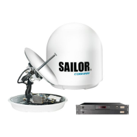
the SAILOR 100 GX ACU to make a full configuration of the SAILOR 100 GX.
You can use a standard Internet browser.
For quick start instructions see Calibration on page 6-4.
6.1.2 Connecting to the web interface
To connect to the web interface of the ACU do as follows:
1. Switch on the ACU. Wait until the LEDs on the front plate of the ACU
show that the system is ready to be configured.
•Power LED: Green
• Logon LED: Off
• Fail/Pass LED: Flashing green during power-on self test, after that
steady green.
2. Connect a PC to LAN port 3: Service (standard Ethernet) of the ACU or to
the front LAN connector of the ACU.
The SAILOR 100 GX system is not designed to be connected
directly to the Internet. It must be located behind a
dedicated network security device such as a fire wall.
If any ports of the SAILOR 100 GX are exposed to the
Internet you must change the default passwords as anyone
with access and malicious intent can render the SAILOR 100
GX inoperable.

 Loading...