Interfaces of the ACU
99-145912-A Chapter 4: Interfaces 4-3
4.1.4 Rx In and Tx Out connectors
The ACU has an Rx Out and a Tx In connector. Use these connectors to
connect the ACU to the GMU.
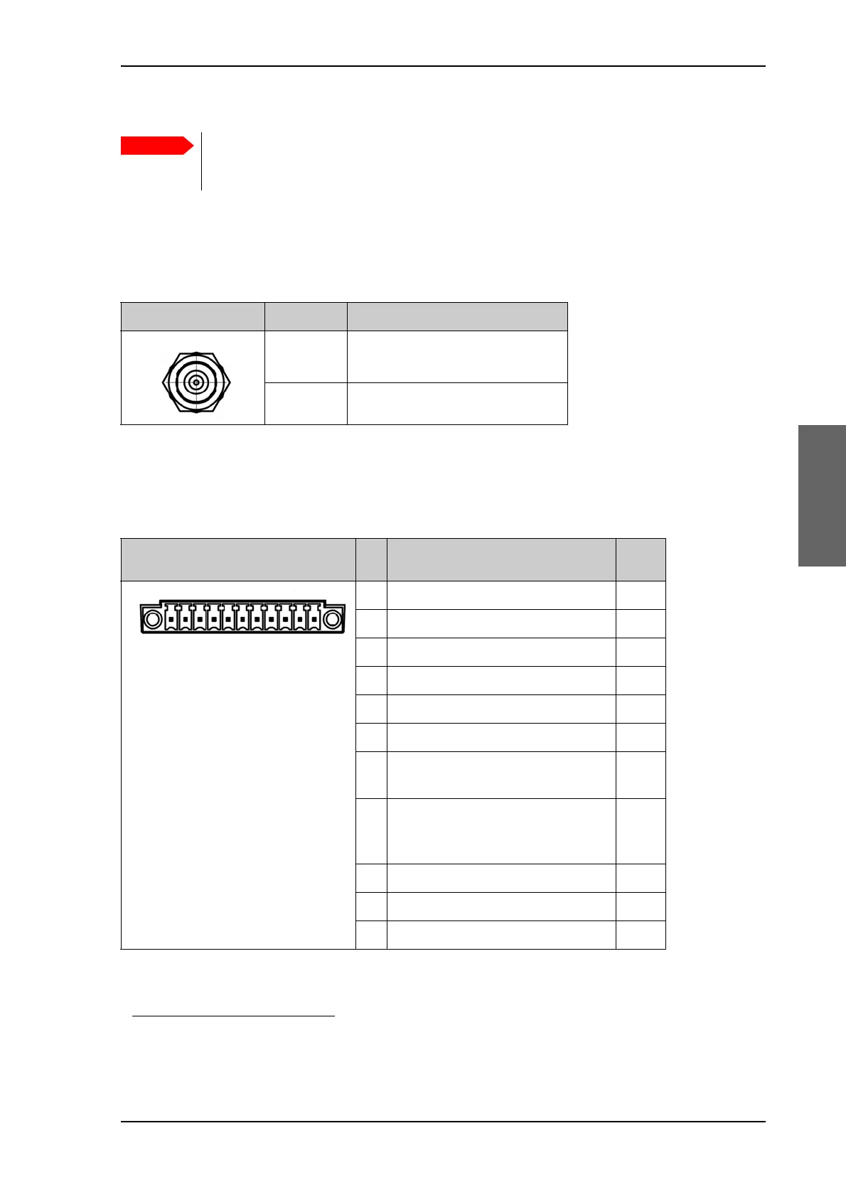
4.1.5 NMEA 0183
1
connector
The ACU has an NMEA 0183 connector for the ship’s gyro.
1. Connect the pins according to the table above.
Do not use TNC connectors on the ADU antenna cable or
on pigtails. TNC connectors cannot carry the DC current
for operating the ADU.
Outline (on the ACU) Pin number Pin function
1 Inner conductor:
reference clock, Rx/Tx
2 Outer conductor: GND (Shield)
Table 4-3: F connector, Rx and Tx, outline and pin assignment
1. (Hardware prepared for NMEA 2000, for future use). NMEA 2000 power: 9-16 VDC. NMEA 2000 LEN (Load
Equivalency Number): 2 (100mA)
Outline (on the ACU) Pin Pin function
Wire
color
1 Not connected –
2 NET-H (NMEA 2000) White
3 NET-L (NMEA 2000) Blue
4 NET-S (NMEA 2000) Red
5 NET-C (NMEA 2000) Black
6 Not connected –
7 Not connected / RS-232 RX
NMEA 0183
–
8 RS-232 GND
RS-422 shield, connect only one
end.
9 RS-422 Line B (+) NMEA 0183
10 RS-422 Line A (-) NMEA 0183
11 Not connected –
Table 4-4: NMEA 0183/2000 connector, outline and pin assignment

 Loading...


