Installation check list: ACU and GMU, connectors and wiring
99-145912-A Chapter 7: Installation check 7-3
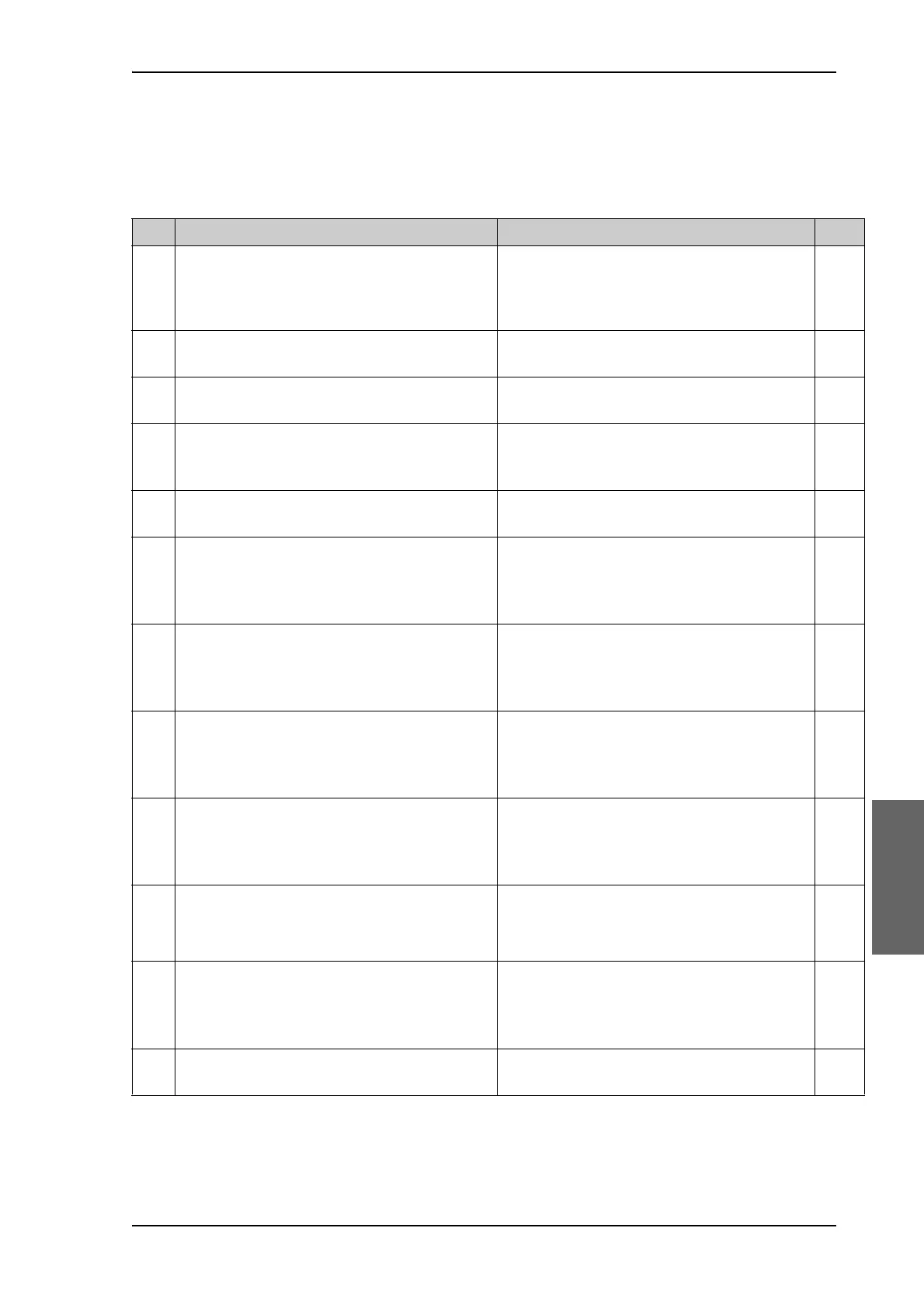
7.2 Installation check list: ACU and GMU, connectors
and wiring
Step Task Verification and further information Done
1.
Check that the ACU is grounded correctly,
using the mounting bolts and washers.
See To ground the ACU on page 3-24
and
Ground and RF protection on page B-1.
2.
Make sure you strain relieved the cables at the
ACU.
See To install the ACU on page 3-24.
3.
Make sure that the GMU is mounted close to
the ACU (preferably next to it).
See To install the GMU on page 3-25.
4.
Check that the ADU antenna N-connector is
properly connected with the 50 Ohm RF cable.
Visual inspection of the cover plate at the
bottom of the ADU. See the figure Connecting
the ADU cable on page 3-20.
5.
Check that the ACU antenna N-connector is
properly connected with the 50 ohm RF cable.
Visual inspection of the connector panel of the
ACU.
6.
Check that the ACU's Rx Out is connected to
the GMU Rx in using the included 1 m F-F 75
ohm cable.
Visual inspection of the connector panel of the
ACU and the VSAT modem. See the figure To
connect the ADU, ACU and GMU on page 3-
26.
7.
Check that the ACU's Tx In is connected to the
GMU Tx out using the included 1 m F-F 75
ohm cable.
Visual inspection of the connector panel of the
ACU and the VSAT modem. See the figure To
connect the ADU, ACU and GMU on page 3-
26.
8.
Check that the ACU's RS-232 is connected to
the GMU RS-232 using the included serial
cable.
Visual inspection of the connector panel of the
ACU and the VSAT modem. See the figure To
connect the ADU, ACU and GMU on page 3-
26.
9.
Check that the ACU's RS-232 is connected to
the GMU RS-422 using the included serial
cable.
Visual inspection of the connector panel of the
ACU and the VSAT modem. See the figure To
connect the ADU, ACU and GMU on page 3-
26.
10.
Check that the ADU's NMEA 0183 connector is
connected to the NMEA 0183 bus of the vessel
using the included multi-connector
Visual inspection of the connector panel of the
ACU connector. See Table 4-4 on page 4-3.
11.
Measure that the power for the ACU has the
correct polarity in the power connector, before
connecting it to the ACU power input.
(V
in
+: left, V
in
-: right).
Use a volt meter. See Table 4-1: DC Input
plug, outline and pin assignment on page 4-2.
12.
Check that the AC power cable is plugged into
the GMU and that AC power is available.
Visual inspection.
Table 7-2: Installation check list: ACU, connectors and wiring

 Loading...


