Removal and replacement of ADU modules
8-32 Chapter 8: Service & maintenance 99-145912-A
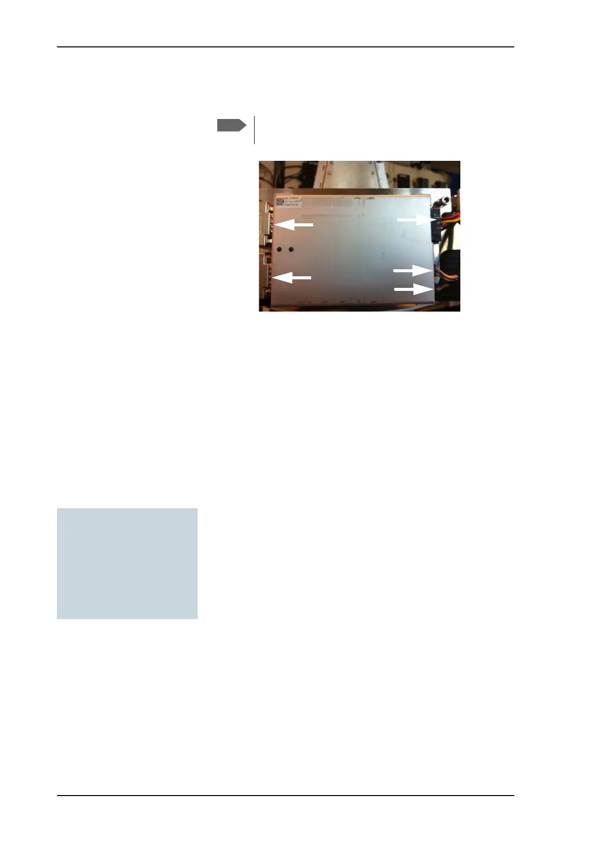
5. Disconnect the 3 connectors at the right of the Azimuth DDM, then
the 2 SUB-D connectors at the left of the Azimuth DDM.
6. Remove the 4x4 mm Allen screws (thread size M5) (visible when the
connectors are removed) and remove the Azimuth DDM.
To insert a new Azimuth DDM follow the instructions above in reverse
order.
8.6.5 To replace the BUC Control Module
(BCM)
To remove the BCM, do as follows:
1. Open the service hatch.
2. Switch off the power to the antenna on the service switch.
3. Rotate the Antenna Dish to top position.
4. Press in and turn the elevation locking pin to locked position.
Note that two connectors are identical. Mark them so you
know where each connector belongs to (e.g. left, right).
Figure 8-31: Azimuth DDM, connectors
Tools needed:
•TX20
• 4 x 150 mm Allen key
(located inside the service
door of the ADU)
•Flat head screw driver

 Loading...


