Removal and replacement of ADU modules
99-145912-A Chapter 8: Service & maintenance 8-31
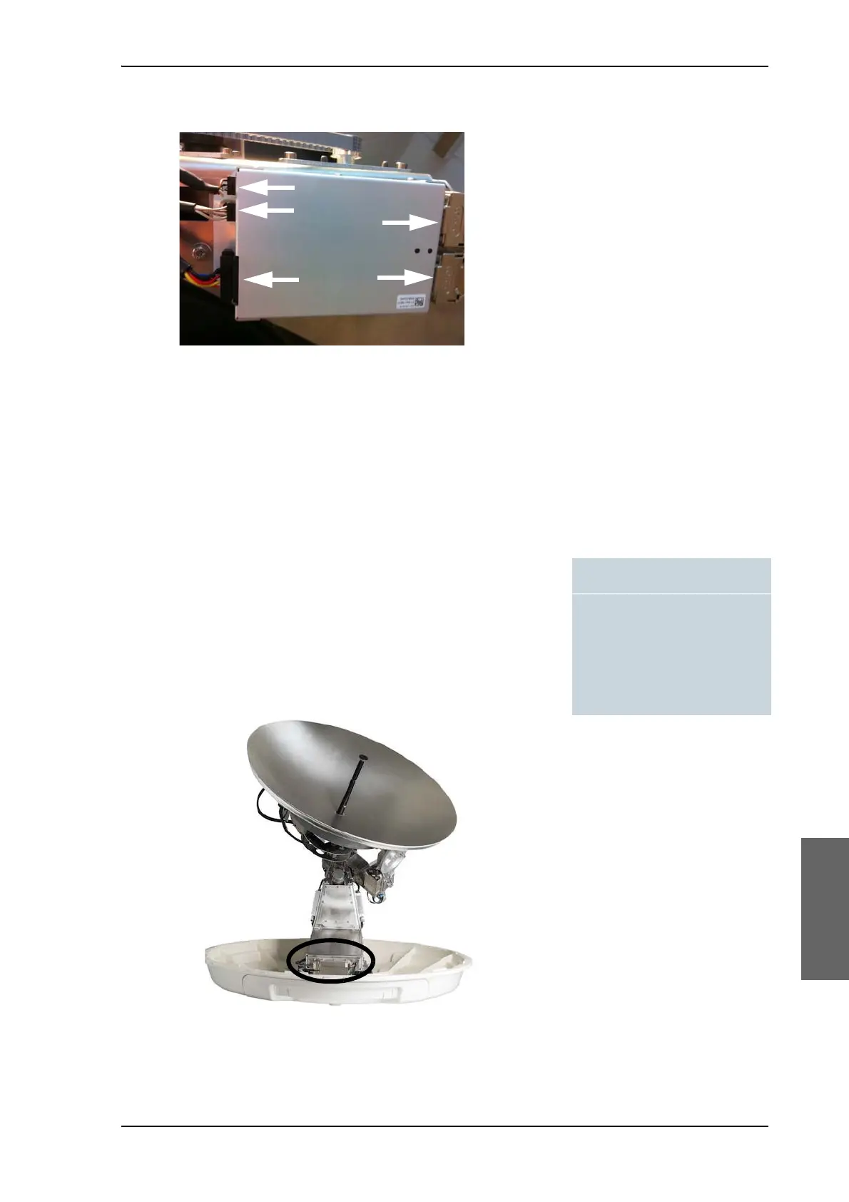
5. Remove the 4x4 mm Allen screws (thread size M5) (visible when the
connectors are removed) and remove the Elevation DDM.
To insert a new Elevation DDM follow the instructions above in reverse
order.
8..6.4.3 To replace the Azimuth DDM
To remove the Azimuth DDM, do as follows:
1. Open the service hatch.
2. Switch off the power to the antenna on the service switch.
3. Rotate the antenna pedestal so that the Azimuth DDM faces the
service hatch.
4. Locate the Azimuth DDM at the front of the antenna.
Figure 8-29: Elevation DDM, connectors
Tools needed:
•TX20
• 4 x 150 mm Allen key
(located inside the service
door of the ADU)
•Flat head screw driver
Figure 8-30: location of the Azimuth DDM (SAILOR 900 picture)

 Loading...


